General Description
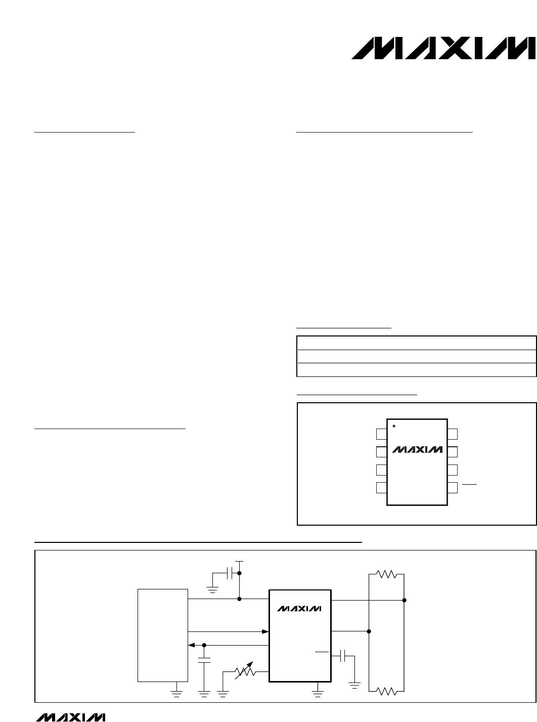
The MAX3050/MAX3057 interface between the CAN
protocol controller and the physical wires of the bus
lines in a controller area network (CAN). They are pri-
marily intended for automotive systems requiring data
rates up to 2Mbps and feature ±80V fault protection
against short circuits in high-voltage power buses. They
provide differential transmit capability to the bus and
differential receive capability to the CAN controller.
The MAX3050/MAX3057 have four modes of operation:
high speed, slope control, standby, and shutdown.
High-speed mode allows data rates up to 2Mbps. In
slope-control mode, data rates are 40kbps to 500kbps,
so the effects of EMI are reduced, and unshielded
twisted or parallel cable can be used. In standby mode,
the transmitters are shut off and the receivers are put
into low-current mode. In shutdown mode, the transmit-
ter and receiver are switched off.
The MAX3050 has an AutoShutdown™ function that
puts the device into a 15µA shutdown mode when the
bus or CAN controller is inactive for 4ms or longer.
The MAX3050/MAX3057 are available in an 8-pin SO
package and are specified for operation from -40°C to
+125°C.
Applications
Automotive Systems
HVAC Controls
Telecom 72V systems
Features
±80V Fault Protection for 42V Systems
Four Operating Modes
High-Speed Operation Up to 2Mbps
Slope-Control Mode to Reduce EMI
(40kbps to 500kbps)
Standby Mode
Low-Current Shutdown Mode
AutoShutdown when Device Is Inactive
(MAX3050)
Automatic Wake-Up from Shutdown (MAX3050)
Thermal Shutdown
Current Limiting
Fully Compatible with the ISO 11898 Standard*
MAX3050/MAX3057
±80V Fault-Protected, 2Mbps, Low Supply
Current CAN Transceivers
________________________________________________________________ Maxim Integrated Products 1
Ordering Information
MAX3050
MAX3057
CAN
CONTROLLER
TXD
V
CC
RXD
RS
GND
CANH
CANL
V
CC
(100nF)
120
120
TX0
RX0
GND
0.1µF
30pF
24k TO 180k
SHDN
( ) ARE FOR 3050 ONLY.
Typical Operating Circuit
19-2670; Rev 0; 10/02
For pricing, delivery, and ordering information, please contact Maxim/Dallas Direct! at
1-888-629-4642, or visit Maxim’s website at www.maxim-ic.com.
PART TEMP RANGE PIN-PACKAGE
MAX3050ASA -40°C to +125°C 8 SO
MAX3057ASA -40°C to +125°C 8 SO
CANL
RXD
1
2
8
7
RS
CANHGND
V
CC
TXD
SO
TOP VIEW
3
4
6
5
MAX3050
MAX3057
SHDN
Pin Configuration
AutoShutdown is a trademark of Maxim Integrated Products, Inc.
* Pending completion of testing.
MAX3050/MAX3057
±80V Fault-Protected, 2Mbps, Low Supply
Current CAN Transceivers
2 _______________________________________________________________________________________
ABSOLUTE MAXIMUM RATINGS
DC ELECTRICAL CHARACTERISTICS
(V
CC
= +5V ±10%, R
L
= 60, RS = GND, T
A
= T
MIN
to T
MAX
. Typical values are at V
CC
= +5V and T
A
= +25°C.)
Stresses beyond those listed under “Absolute Maximum Ratings” may cause permanent damage to the device. These are stress ratings only, and functional
operation of the device at these or any other conditions beyond those indicated in the operational sections of the specifications is not implied. Exposure to
absolute maximum rating conditions for extended periods may affect device reliability.
V
CC
to GND ............................................................ -0.3V to +6V
TXD, RS, RXD, SHDN to GND ....................-0.3V to (V
CC
+ 0.3V)
CANH, CANL to GND..............................................-80V to +80V
RXD Shorted to GND................................................. Continuous
Continuous Power Dissipation (T
A
= +70°C)
8-Pin SO (derate 5.9mW/°C above +70°C) .................470mW
Operating Temperature Range .........................-40°C to +125°C
Junction Temperature......................................................+150°C
Storage Temperature Range .............................-65°C to +150°C
Lead Temperature (soldering, 10s) ................................+300°C
PARAMETER SYMBOL CONDITIONS MIN TYP MAX UNITS
Dominant (Note 1) 56 72
Dominant no load 6
Recessive (Note 1) 3.6 5.5
Supply Current I
S
Recessive no load 5.5
mA
Quiescent Current Standby Mode I
Q
V
RS
= V
CC
125 260 µA
Shutdown Supply Current I
QSHDN
SHDN = GND 15 30 µA
Thermal-Shutdown Threshold 160 °C
Thermal-Shutdown Hysteresis 20 °C
TXD INPUT LEVELS
High-Level Input Voltage V
IH
2V
Low-Level Input Voltage V
IL
0.4 V
High-Level Input Current I
IH
V
TXD
= V
CC
A
Pullup Resistor R
INTXD
20 k
CANH, CANL TRANSMITTER
Recessive Bus Voltage
V
CANH,
V
CANL
V
TXD
= V
CC
, no load 2 3 V
-2V < V
CANH
, V
CANL
< +7V
SHDN = GND, V
TXD
= V
CC
-2 +1
Off-State Output Leakage I
LO
-80V < V
CANH
, V
CANL
< +80V
SHDN = GND, V
TXD
= V
CC
-4 +4
mA
CANH Output Voltage V
CANH
V
TXD
= 0 3.0 V
CC
V
CANL Output Voltage V
CANL
V
TXD
= 0 0 2.0 V
V
TXD
= 0 1.5 5
V
TXD
= 0, R
L
= 45 1.5
V
Differential Output
(V
CANH
- V
CANL
)
V
CANH
,
V
CANL
V
TXD
= V
CC
, no load -500 +50 mV
CANH Short-Circuit Current I
SC
V
CANH
= -5V -200 mA
CANL Short-Circuit Current I
SC
V
CANL
= 18V 200 mA
MAX3050/MAX3057
±80V Fault-Protected, 2Mbps, Low Supply
Current CAN Transceivers
_______________________________________________________________________________________ 3
DC ELECTRICAL CHARACTERISTICS (continued)
(V
CC
= +5V ±10%, R
L
= 60, RS = GND, T
A
= T
MIN
to T
MAX
. Typical values are at V
CC
= +5V and T
A
= +25°C.)
PARAMETER SYMBOL CONDITIONS MIN TYP MAX UNITS
DC BUS RECEIVER (V
TXD
= V
CC
; CANH and CANL externally driven; -2V < V
CANH
, V
CANL
< +7V, unless otherwise specified)
Differential Input Voltage
(Recessive)
V
DIFF
-7V < V
CANH
, V
CANL
< +12V -1.0 +0.5 V
Differential Input Voltage
(Dominant)
V
DIFF
-7V < V
CANH
, V
CANL
< +12V 0.9 3.3 V
Differential Input Hysteresis V
DIFF
(
HYST
)
150 mV
CANH Input Wake-Up Voltage
Threshold
V
CANH
(SHDN)
SHDN = GND, V
TXD
= V
CC
(MAX3050) 6 9 V
RXD High-Level Output Voltage V
OH
I = -100µA
0.8
V
CC
V
I = 10mA 0.8
RXD Low-Level Output Voltage V
OL
I = 5mA 0.4
V
CANH and CANL Input
Resistance
R
I
525k
Differential Input Resistance R
DIFF
10 100 k
MODE SELECTION (RS)
Input Voltage for High Speed V
SLP
0.3
V
CC
V
Input Voltage for Standby V
STBY
0.75
V
CC
V
Slope-Control Mode Voltage V
SLOPE
R
RS
= 24k to 180k
0.4
V
CC
0.6
V
CC
V
Slope-Control Mode Current I
SLOPE
R
RS
= 24k to 180k -200 -10 µA
Standby Mode I
STBY
-10 +10 µA
High-Speed Mode Current I
HS
V
RS
= 0 -500 µA
SHUTDOWN
SHDN Input Pullup Resistor R
INSHDN
MAX3057 500 900 k
SHDN Input Voltage High 2V
SHDN Input Voltage Low 0.5 V

MAX3053ESA+

Mfr. #:
Manufacturer:
Maxim Integrated
Description:
CAN Interface IC 80V Fault-Protected 2Mbps
Lifecycle:
New from this manufacturer.
Delivery:
DHL FedEx Ups TNT EMS
Payment:
T/T Paypal Visa MoneyGram Western Union