MAX3050/MAX3057
±80V Fault-Protected, 2Mbps, Low Supply
Current CAN Transceivers
4 _______________________________________________________________________________________
Note 1: As defined by ISO, bus value is one of two complementary logical values: dominant or recessive. The dominant value repre-
sents the logical 1 and the recessive represents the logical 0. During the simultaneous transmission of the dominant and
recessive bits, the resulting bus value is dominant. For MAX3050 and MAX3057 values, see the truth table in the
Transmitter and Receiver sections.
TIMING CHARACTERISTICS
(V
CC
= +5V ±10%, R
L
= 60Ω, C
L
= 100pF, T
A
= T
MIN
to T
MAX
. Typical values are at V
CC
= +5V and T
A
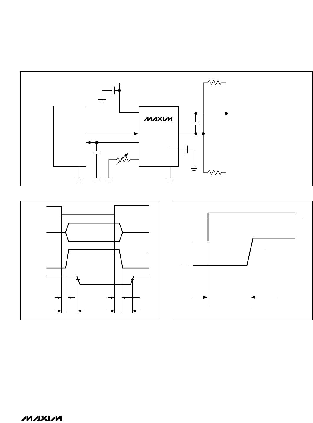
= +25°C.) (Figures 1, 2, and 3)
PARAMETER SYMBOL CONDITIONS MIN TYP MAX UNITS
TIMING
V
RS
= 0 (2Mbps) 0.5
R
RS
= 24kΩ (500kbps) 2
R
RS
= 100kΩ (125kbps) 8
Minimum Bit Time t
BIT
R
RS
= 180kΩ (62.5kbps) 25
µs
Delay TXD to Bus Active t
ONTXD
V
RS
= 0 40 ns
Delay TXD to Bus Inactive t
OFFTXD
V
RS
= 0 75 ns
V
RS
= 0 (2Mbps) 120 ns
R
RS
= 24kΩ (500kbps) 0.4
R
RS
= 100kΩ (125kbps) 1.6
Delay TXD to Receiver Active t
ONRXD
R
RS
= 180kΩ (62.5kbps) 5.0
µs
V
RS
= 0 (2Mbps) 130 ns
R
RS
= 24kΩ (500kbps) 0.45
R
RS
= 100kΩ (125kbps) 1.6
Delay TXD to Receiver Inactive t
OFFRXD
R
RS
= 180kΩ (62.5kbps) 5.0
µs
R
RS
= 24kΩ (500kbps) 14
R
RS
= 100kΩ (125kbps) 7Differential Output Slew Rate SR
R
RS
= 180kΩ (62.5kbps) 1.6
V/µs
Bus Dominant to RXD Low Standby mode 10 µs
Time to Wake Up: CANH > 9V t
WAKE
SHDN = GND, V
TXD
= V
CC
(MAX3050) 10 µs
Time to Sleep Mode when Bus Is
Recessive
t
SHDN
C
SHDN
= 100nF (MAX3050) 10 47 ms