REV. E
AD7701
–15–
Synchronous External Clock Mode (SEC)
The SEC mode (MODE pin grounded) is designed for direct
interface to the synchronous serial ports of industry-standard
microprocessors such as the COPS series, 68HC11, and 68HC05.
The SEC mode also allows customized interfaces, using I/O
port pins, to microprocessors that do not have a direct fit with
the AD7701’s other modes.
As shown in Figure 20, a falling edge on CS enables the serial
data output with the MSB initially valid. Subsequent data bits
change on the falling edge of an externally supplied SCLK.
After the LSB has been transmitted, DRDY goes high and
SDATA goes three-state. If CS is low and the AD7701 is still
transmitting data when a new data-word becomes available, the
old data-word continues to be transmitted and the new data is lost.
If CS is taken high at any time during data transmission, SDATA
and SCLK will go three-state immediately. If CS returns low,
the AD7701 will continue transmission with the same data bit.
If transmission has not been initiated and completed by the time
the next data-word becomes available, and if CS is high, DRDY
will return high for four clock cycles, then fall as the new word
is loaded into the output register.
CLKIN (I)
DRDY (O)
SDATA (O)
DB15 (MSB)
DB14
DB2
DB1
DB0 (LSB)
HI-Z
HI-Z
SCLK (O)
HI-Z
HI-Z
CS (I)
72 CLKIN
CYCLES
Figure 19. SSC Mode Showing Data Timing Relative to SCLK
SCLK (I)
SDATA (O)
DB15
(MSB)
DB14
DB13
DB1
DB0
(LSB)
HI-Z
HI-Z
DRDY (O)
CS (I)
Figure 20. Timing Diagram for the SEC Mode
REV. E–16–
AD7701
Asynchronous Communications (AC) Mode
The AC mode (MODE pin tied to –5 V) offers a UART com-
patible interface that allows the AD7701 to transmit data
asynchronously from remote locations. An external SCLK sets
the baud rate and data is transmitted in two bytes in UART
compatible format. Using the AC mode, the AD7701 can be
interfaced directly to microprocessors with UART interfaces,
such as the 8051 and TMS70X2.
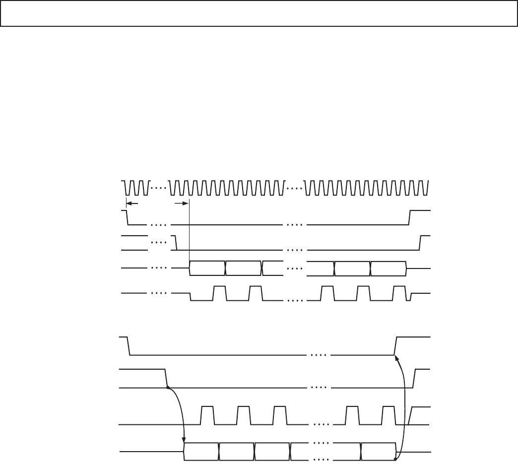
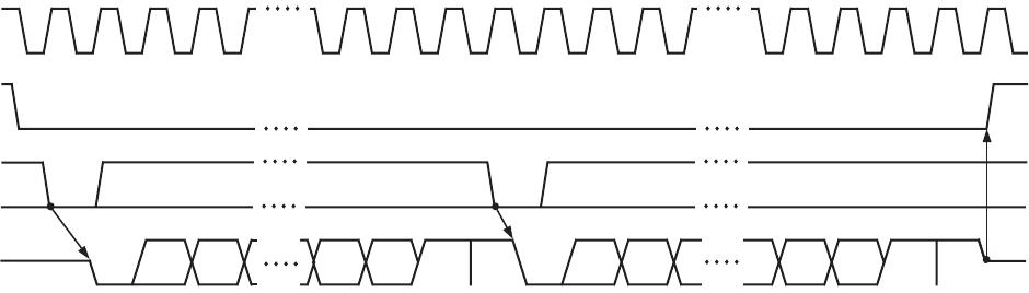
Data transmission is initiated by CS going low. If CS is low on a
falling edge of SCLK, the AD7701 begins transmitting an 8-bit
data byte (DB8 to DB15) with one start bit and two stop bits,
as in Figure 21. The SDATA output will then go three-state.
The second byte is transmitted by bringing CS low again and
DB0 to DB7 are transmitted in the same format as the first byte.
UART baud rates are typically low compared to the AD7701’s
4 kHz output update rate. If CS is low and data is still being
transmitted when a new data-word becomes available, the new
data will be ignored. However, if CS has been taken high between
bytes, when a new data-word becomes available, the AD7701
could update the output register before the second byte is trans-
mitted. In this case, the UART would receive the first byte of
the new word instead of the second byte of the old word. When
using the AC mode, care must obviously be taken to ensure that
this does not occur.
DIGITAL NOISE AND OUTPUT LOADING
As mentioned earlier, the AD7701 divides its internal timing
into two distinct phases, analog sampling and settling and digi-
tal computation. In the SSC mode, data is transmitted only
during the digital computation periods to minimize the effects
of digital noise on analog performance. In the SEC and AC
modes, data transmission is externally controlled, so this auto-
matic safeguard does not exist.
Whatever mode of operation is used, resistive and capacitive
loads on digital outputs should be minimized in order to reduce
crosstalk between analog and digital portions of the circuit. For
this reason, connection to low power CMOS logic such as one
of the 4000 series or 74C families is recommended.
It is especially important to minimize the load on SDATA in the
AC mode, as transmission in this mode is inherently asynchro-
nous. In the SEC mode, the AD7701 should be synchronized to
the digital system clock via CLKIN.
SCLK (I)
SDATA (O)
DB9
START
BIT
DB8
DB14 DB15
STOP
BIT
DB0 DB1
DB6
DB7
HI-Z
STOP
BIT
START
BIT
STOP
BIT
STOP
BIT
DRDY (O)
CS (I)
Figure 21. Timing Diagram for Asynchronous Communications Mode
REV. E
AD7701
–17–
OUTLINE DIMENSIONS
20-Lead Plastic Dual In-Line Package [PDIP]
(N-20)
Dimensions shown in inches and (millimeters)
20
1
10
11
0.985 (25.02)
0.965 (24.51)
0.945 (24.00)
0.295 (7.49)
0.285 (7.24)
0.275 (6.99)
0.150 (3.81)
0.135 (3.43)
0.120 (3.05)
0.015 (0.38)
0.010 (0.25)
0.008 (0.20)
0.325 (8.26)
0.310 (7.87)
0.300 (7.62)
SEATING
PLANE
0.015 (0.38) MIN
0.180 (4.57)
MAX
0.022 (0.56)
0.018 (0.46)
0.014 (0.36)
0.150 (3.81)
0.130 (3.30)
0.110 (2.79)
0.100
(2.54)
BSC
0.060 (1.52)
0.050 (1.27)
0.045 (1.14)
CONTROLLING DIMENSIONS ARE IN INCHES; MILLIMETER DIMENSIONS
(IN PARENTHESES) ARE ROUNDED-OFF INCH EQUIVALENTS FOR
REFERENCE ONLY AND ARE NOT APPROPRIATE FOR USE IN DESIGN
COMPLIANT TO JEDEC STANDARDS MO-095-AE
20-Lead Standard Small Outline Package [SOIC]
Wide Body
(R-20)
Dimensions shown in millimeters and (inches)
CONTROLLING DIMENSIONS ARE IN MILLIMETERS; INCH DIMENSIONS
(IN PARENTHESES) ARE ROUNDED-OFF MILLIMETER EQUIVALENTS FOR
REFERENCE ONLY AND ARE NOT APPROPRIATE FOR USE IN DESIGN
COMPLIANT TO JEDEC STANDARDS MS-013AC
0.75 (0.0295)
0.25 (0.0098)
20 11
10
1
0.32 (0.0126)
0.23 (0.0091)
8
0
45
1.27 (0.0500)
0.40 (0.0157)
SEATING
PLANE
0.30 (0.0118)
0.10 (0.0039)
0.51 (0.0201)
0.33 (0.0130)
2.65 (0.1043)
2.35 (0.0925)
1.27
(0.0500)
BSC
10.65 (0.4193)
10.00 (0.3937)
7.60 (0.2992)
7.40 (0.2913)
13.00 (0.5118)
12.60 (0.4961)
COPLANARITY
0.10
20-Lead Ceramic Dual In-Line Pacakage [CERDIP]
(Q-20)
Dimensions shown in inches and (millimeters)
20
110
11
0.310 (7.87)
0.220 (5.59)
PIN 1
0.005
(0.13)
MIN
0.098 (2.49)
MAX
15
0
0.320 (8.13)
0.290 (7.37)
0.015 (0.38)
0.008 (0.20)
SEATING
PLANE
0.200 (5.08)
MAX
1.060 (26.92) MAX
0.150 (3.81)
MIN
0.200 (5.08)
0.125 (3.18)
0.023 (0.58)
0.014 (0.36)
0.100
(2.54)
BSC
0.070 (1.78)
0.030 (0.76)
0.060 (1.52)
0.015 (0.38)
CONTROLLING DIMENSIONS ARE IN INCHES; MILLIMETERS DIMENSIONS
(IN PARENTHESES) ARE ROUNDED-OFF INCH EQUIVALENTS FOR
REFERENCE ONLY AND ARE NOT APPROPRIATE FOR USE IN DESIGN
28-Lead Shrink Small Outline Package [SSOP]
(RS-28)
Dimensions shown in millimeters
0.25
0.09
0.95
0.75
0.55
8
4
0
0.05
MIN
1.85
1.75
1.65
2.00 MAX
0.38
0.22
SEATING
PLANE
0.65
BSC
0.10
COPLANARITY
28 15
14
1
10.50
10.20
9.90
5.60
5.30
5.00
8.20
7.80
7.40
COMPLIANT TO JEDEC STANDARDS MO-150AH

AD7701AN

Mfr. #:
Manufacturer:
Description:
Analog to Digital Converters - ADC 16-Bit IC
Lifecycle:
New from this manufacturer.
Delivery:
DHL FedEx Ups TNT EMS
Payment:
T/T Paypal Visa MoneyGram Western Union