LTC2925
19
2925fd
For more information www.linear.com/LTC2925
applicaTions inForMaTion
Final Sanity Checks
The collection of equations below is useful for identifying
unrealizable solutions.
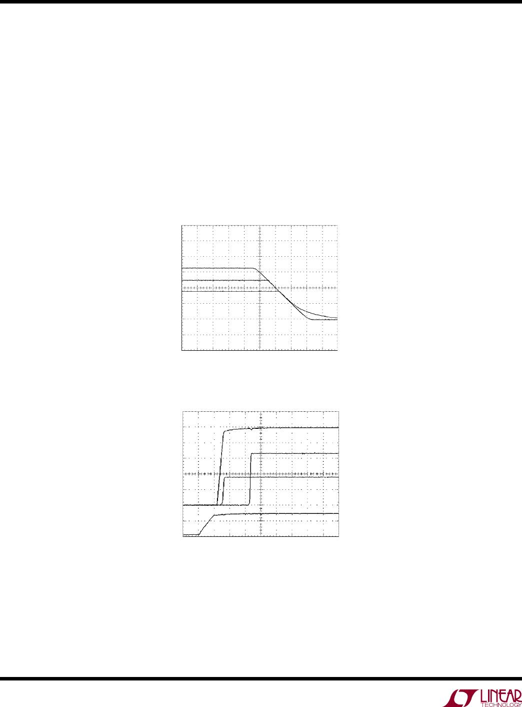
As stated in step 2, the slave supply must finish ramping
before the master signal has reached its final voltage. This
can be verified by the following equation:
V
R
R
V
TRACK
TB
TA
1+
⎛
⎝
⎜
⎞
⎠
⎟
<
Here, V
TRACK
= 0.8V. V
MASTER
is the final voltage of the
master signal, either the supply voltage ramped up through
the optional external FET or V
CC
when no FET is present.
It is possible to choose resistor values that require the
LTC2925 to supply more current than the Electrical Char
-
acteristics table guarantees. To avoid this condition, check
that I
TRACKx
does not exceed 1mA and I
RAMPBUF
does not
exceed ±3mA.
To confirm that I
TRACKx
< 1mA, the TRACKx pin(s) maxi-
mum guaranteed current, verify that:
RR
mA
TRACK
TA TB
< 1
Finally, check that the RAMPBUF pin will not be forced to
sink more than 3mA when it is at 0V or be forced to source
more than 3mA when it is at V
MASTER
.
R
R
R
3mA and
V
RR
V
RR
V
RR
3mA
TRACK
TB1
TRACK
TB2
TRACK
TB3
MASTER
MASTER
MASTER
++<
+
+
+
+
+
<
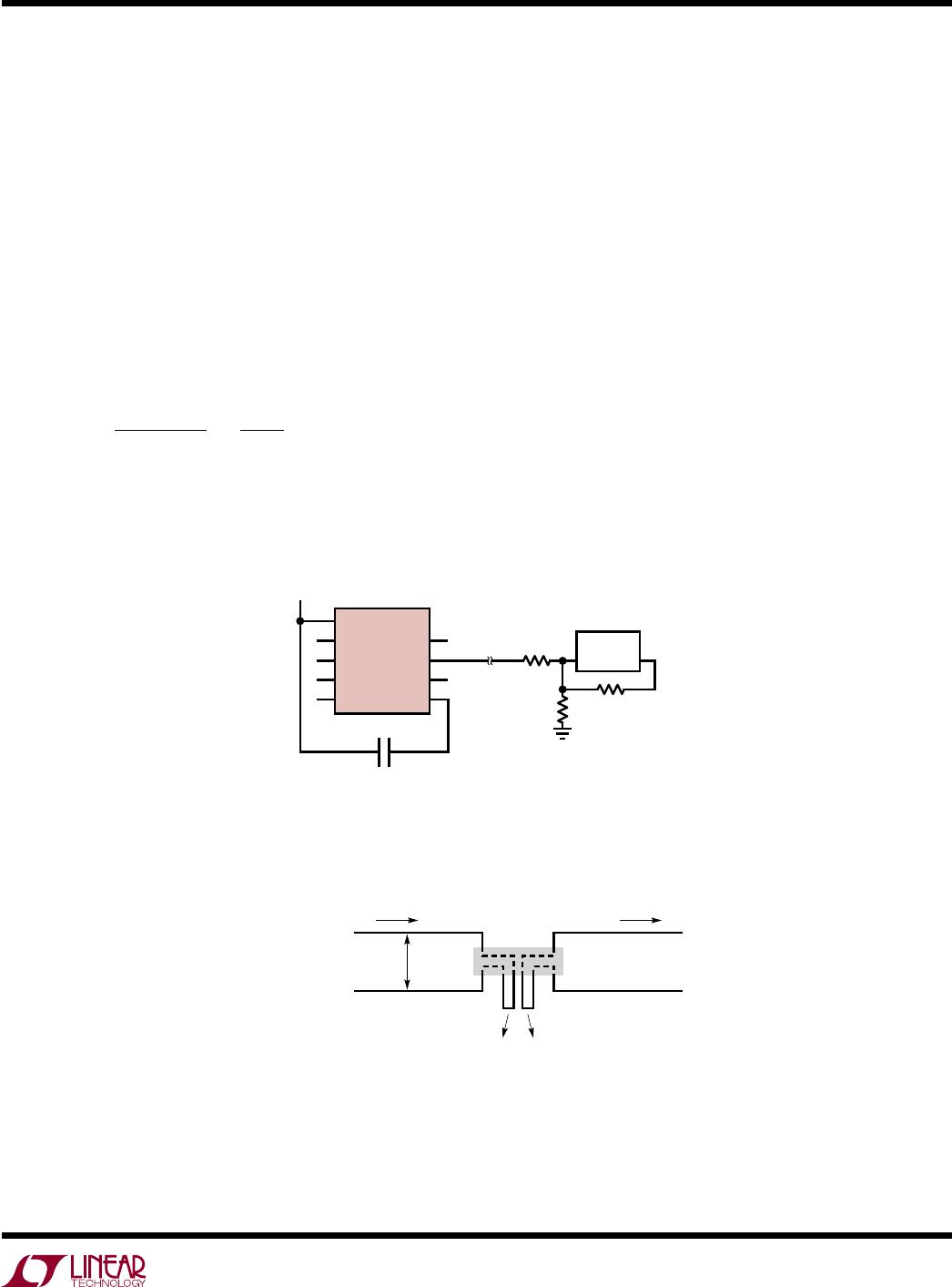
Caution with Boost Regulators and Linear Regulators
Note that the LTC2925’s tracking cell is not able to control
the outputs of all types of power supplies. If it is necessary
to control a supply, where the output is not controllable
through its feedback node, the series FET can be used to
control its output. For example, boost regulators commonly
contain an inductor and diode between the input supply
and the output supply providing a DC current path when
the output voltage falls below the input voltage. Therefore,
the LTC2925’s tracking cell will not effectively drive the
supply’s output below the input.
Special caution should be taken when considering the use
of linear regulators. Three-terminal linear regulators have
a reference voltage that is referred to the output supply
rather than to ground. In this case, driving current into
the regulator’s feedback node will cause its output to rise
rather than fall. Even linear regulators that have their ref
-
erence voltage referred to ground, including low-dropout
regulators (LDOs), may be problematic. Linear regulators
commonly contain cir
cuitr
y that prevents driving their
outputs below their reference voltage. This may not be
obvious from the data sheets, so lab testing is recom
-
mended whenever the LTC2925’s tracking cell is used to
control linear regulators.