MAX3541
Complete Single-Conversion
Television Tuner
______________________________________________________________________________________ 13
BIT NAME BIT LOCATION (0 = LSB)
RECOMMENDED
DEFAULT
FUNCTION
TFS[7:0] 7-0 00001111* Programs series capacitor values in the tracking filter.
Table 9. Tracking Filter Series Capacitor Register (Address: 0111
b
)
*See the
RF Tracking Filter
section.
BIT NAME BIT LOCATION (0 = LSB)
RECOMMENDED
DEFAULT
FUNCTION
TFR[7:0] 7-0 00000000* Tracking filter data bits read from the device’s ROM table.
Table 13. ROM Table Data Readback Register (Address: 1011
b
)
*See the
RF Tracking Filter
section.
BIT NAME BIT LOCATION (0 = LSB)
RECOMMENDED
DEFAULT
FUNCTION
RESERVED 7-0 N/A Reserved. Do not program these bits during normal operation.
Table 12. Reserved Register (Address: 1010
b
)
*See the
RF Tracking Filter
section.
*See the
RF Tracking Filter
section.
BIT NAME BIT LOCATION (0 = LSB)
RECOMMENDED
DEFAULT
FUNCTION
FLD 7 0
Filter load bit. A 0 to 1 transition of this bit forces the loading of the
ROM Table Data Readback register.
RESERVED 6 0 Must be set to 0.
TFP[5:0] 5-0 001001* Programs parallel capacitor values in the tracking filter.
Table 10. Tracking Filter Parallel Capacitor Register (Address: 1000
b
)
BIT NAME BIT LOCATION (0 = LSB)
RECOMMENDED
DEFAULT
FUNCTION
RESERVED 7-4 0000 Must be set to 0000.
TFA[3:0] 3-0 0000* Address bits of the ROM register to be read.
Table 11. Tracking Filter ROM Address Register (Address: 1001
b
)
BIT NAME BIT LOCATION (0 = LSB)
RECOMMENDED
DEFAULT
FUNCTION
POR 7 N/A
Power-on reset.
0 = Status register has been read
1 = Power reset since last status register read
LD[2:0] 6-4 N/A
VCO tuning voltage indicators.
000 = PLL not in lock, tune to the next lowest sub-band
001–110 = PLL in lock
111 = PLL not in lock, tune to the next higher sub-band
RESERVED 3-0 N/A Reserved.
Table 14. Status Register (Address: 1100
b
)
MAX3541
2-Wire Serial Interface
The MAX3541 use a 2-wire I
2
C-compatible serial inter-
face consisting of a serial-data line (SDA) and a serial-
clock line (SCL). SDA and SCL facilitate bidirectional
communication between the MAX3541 and the master at
clock frequencies up to 400kHz. The master initiates a
data transfer on the bus and generates the SCL signal to
permit data transfer. The MAX3541 behaves as a slave
device that transfers and receives data to and from the
master. Pull SDA and SCL high with external pullup
resistors (1kΩ or greater) for proper bus operation.
One bit is transferred during each SCL clock cycle. A
minimum of nine clock cycles is required to transfer a
byte in or out of the MAX3541 (8 data bits and an
ACK/NACK). The data on SDA must remain stable during
the high period of the SCL clock pulse. Changes in SDA
while SCL is high and stable are considered control sig-
nals (see the
START and STOP Conditions
section). Both
SDA and SCL remain high when the bus is not busy.
START and STOP Conditions
The master initiates a transmission with a START condi-
tion (S), which is a high-to-low transition on SDA while
SCL is high. The master terminates a transmission with
a STOP condition (P), which is a low-to-high transition
on SDA while SCL is high.
Acknowledge and Not-Acknowledge Conditions
Data transfers are framed with an acknowledge bit
(ACK) or a not-acknowledge bit (NACK). Both the mas-
ter and the MAX3541 (slave) generate acknowledge
bits. To generate an acknowledge, the receiving device
must pull SDA low before the rising edge of the
acknowledge-related clock pulse (ninth pulse) and
keep it low during the high period of the clock pulse.
To generate a not-acknowledge condition, the receiver
allows SDA to be pulled high before the rising edge of
the acknowledge-related clock pulse, and leaves SDA
high during the high period of the clock pulse.
Monitoring the acknowledge bits allows for detection of
unsuccessful data transfers. An unsuccessful data
transfer happens if a receiving device is busy or if a
system fault has occurred. In the event of an unsuc-
cessful data transfer, the bus master must reattempt
communication at a later time.
Slave Address
The MAX3541 has a 7-bit slave address that must be
sent to the device following a START condition to initi-
ate communication. The slave address is determined
by the state of the ADDR2 and ADDR1 pins and is
equal to 11000[ADDR2][ADDR1]. The eighth bit (R/W)
following the 7-bit address determines whether a read
or write operation occurs. Table 15 shows the possible
address configurations.
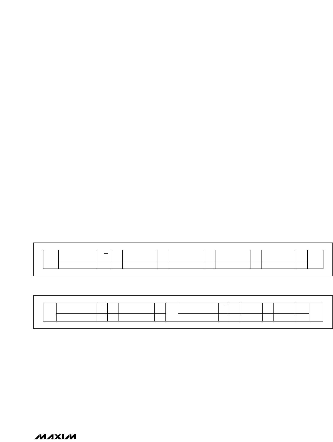
The MAX3541 continuously awaits a START condition
followed by its slave address. When the device recog-
nizes its slave address, it acknowledges by pulling the
SDA line low for one clock period; it is ready to accept
or send data depending on the R/W bit (Figure 1).
Complete Single-Conversion
Television Tuner
14 ______________________________________________________________________________________
SCL
SDA
123456789
S 1 1 0 0 0 ADDR2 ADDR1 R/W ACK
SLAVE ADDRESS
P
NOTE: TIMING PARAMETERS CONFORM WITH I
2
C BUS SPECIFICATIONS.
Figure 1. MAX3541 Slave Address Byte
ADDR2 ADDR1 WRITE ADDRESS READ ADDRESS
0 0 0xC0 0xC1
0 1 0xC2 0xC3
1 0 0xC4 0xC5
1 1 0xC6 0xC7
Table 15. MAX3541 Address Configurations
Write Cycle
When addressed with a write command, the MAX3541
allows the master to write to a single register or to multi-
ple successive registers.
A write cycle begins with the bus master issuing a
START condition followed by the seven slave address
bits and a write bit (R/W = 0). The MAX3541 issues an
ACK if the slave address byte is successfully received.
The bus master must then send to the slave the
address of the first register it wishes to write to. If the
slave acknowledges the address, the master can then
write one byte to the register at the specified address.
Data is written beginning with the most significant bit.
The MAX3541 again issues an ACK if the data is suc-
cessfully written to the register. The master can contin-
ue to write data to the successive internal registers with
the MAX3541 acknowledging each successful transfer,
or it can terminate transmission by issuing a STOP con-
dition. The write cycle does not terminate until the mas-
ter issues a STOP condition.
Figure 2 illustrates an example in which registers 0
through 2 are written with 0x0E, 0xD8, and 0xE1,
respectively.
Read Cycle
A read cycle begins with the bus master issuing a
START condition followed by the seven slave address
bits and a write bit (R/W = 0). The MAX3541 issues an
ACK if the slave address byte is successfully
received. The master then sends the 8-bit address of
the first register that it wishes to read. The MAX3541
then issues another ACK. Next, the master must issue
a START condition followed by the 7 slave address
bits and a read bit (R/W = 1). The MAX3541 issues an
ACK if it successfully recognizes its address and
begins sending data from the specified register
address starting with the most significant bit (MSB).
Data is clocked out of the MAX3541 on the rising
edge of SCL. On the 9th rising edge of SCL, the mas-
ter can issue an ACK and continue reading succes-
sive registers or it can issue a NACK followed by a
STOP condition to terminate transmission. The read
cycle does not terminate until the master issues a
STOP condition. Figure 3 illustrates an example in
which registers 0 and 1 are read back.
MAX3541
Complete Single-Conversion
Television Tuner
______________________________________________________________________________________ 15
START
WRITE DEVICE
ADDRESS
R/W
11000[ADDR2][ADDR1] 0 ————
WRITE REGISTER
ADDRESS
0x00
ACK ACK ACK ACK ACK
WRITE DATA TO
REGISTER 0x00
0x0E
WRITE DATA TO
REGISTER 0x01
0xD8
WRITE DATA TO
REGISTER 0x02
0xE1
STOP
Figure 2. Example: Write Registers 0 Through 2 with 0x0E, 0xD8, and 0xE1, Respectively
START
WRITE DEVICE
ADDRESS
R/W
110000[ADDR2][ADDR1]
WRITE DEVICE
ADDRESS
110000[ADDR2][ADDR1]0
WRITE 1ST REGISTER
ADDRESS
0x00
ACK NACK
ACK
READ DATA
REG 0
D7–D0
STOP
R/W
1—
ACK
READ DATA
REG 1
D7–D0
ACK
START
Figure 3. Example: Read Data from Registers 0 and 1

MAX3541ELM+

Mfr. #:
Manufacturer:
Maxim Integrated
Description:
Tuners Single-Conversion Television Tuner
Lifecycle:
New from this manufacturer.
Delivery:
DHL FedEx Ups TNT EMS
Payment:
T/T Paypal Visa MoneyGram Western Union

Products related to this Datasheet