IRS2982SPBF
13 2017-02-07
Internal high voltage regulator
The internal high voltage regulator supplies the IC
low voltage bias supply VCC during startup,
allowing operation directly from a DC input voltage
up to 600V. To begin operating the IRS2982
requires VCC to be raised above the under
voltage lockout positive threshold (V
CCUV+
)
and to
continue operating VCC must be maintained
above the under voltage lockout negative
threshold (V
CCUV-
)
.
The HV regulator enables an IRS2982 based LED
driver to start up very rapidly and deliver light
within 0.5s of switch on at any line input voltage.
When the switching converter is operating VCC is
normally supplied through an auxiliary transformer
winding. The HV regulator switches over to
support mode when steady state operation is
reached in which VCC is held above V
CCUV+
to
maintain operation under light load or fault
conditions.
As well as supplying VCC the Flyback
inductor/transformer auxiliary winding provides
output voltage and zero-crossing (ZX) information
for critical conduction mode (CrCM) operation.
In the event of a short circuit at the output, the
VCC supply derived from the auxiliary winding
normally collapses below V
CCUV-
causing the
IRS2982 to shut off. The startup sequence then
begins again in a continuous hiccup mode until
the short circuit is removed thereby preventing
damage to the circuit.
Figure 1: HV regulator characteristics
Figure 1 illustrates the characteristics of the high
voltage regulator. At switch on it operates in
startup mode during which current is supplied to
VCC from the HV input connected to the rectified
high voltage bus. The current supplied depends on
the voltage at VCC and gradually falls as VCC
rises until it cuts off completely at V
HVS_OFF1
. During
normal operation when the voltage at the FB input
exceeds VREF for the first time the HV regulator
switches over to support mode, where current is
suppled to VCC only when the voltage drops
below V
HVS_OFF2
, which is close to V
CCUV+
. This
helps to sustain the VCC supply at light loads such
as during dimming. Once in support mode the
IRS2982 will not revert to start-up mode until VCC
drops below V
CCUV-.
Sustained operation of the HV regulator may is
likely to cause heating and should be avoided.
Further information is given in the performance
graphs section.
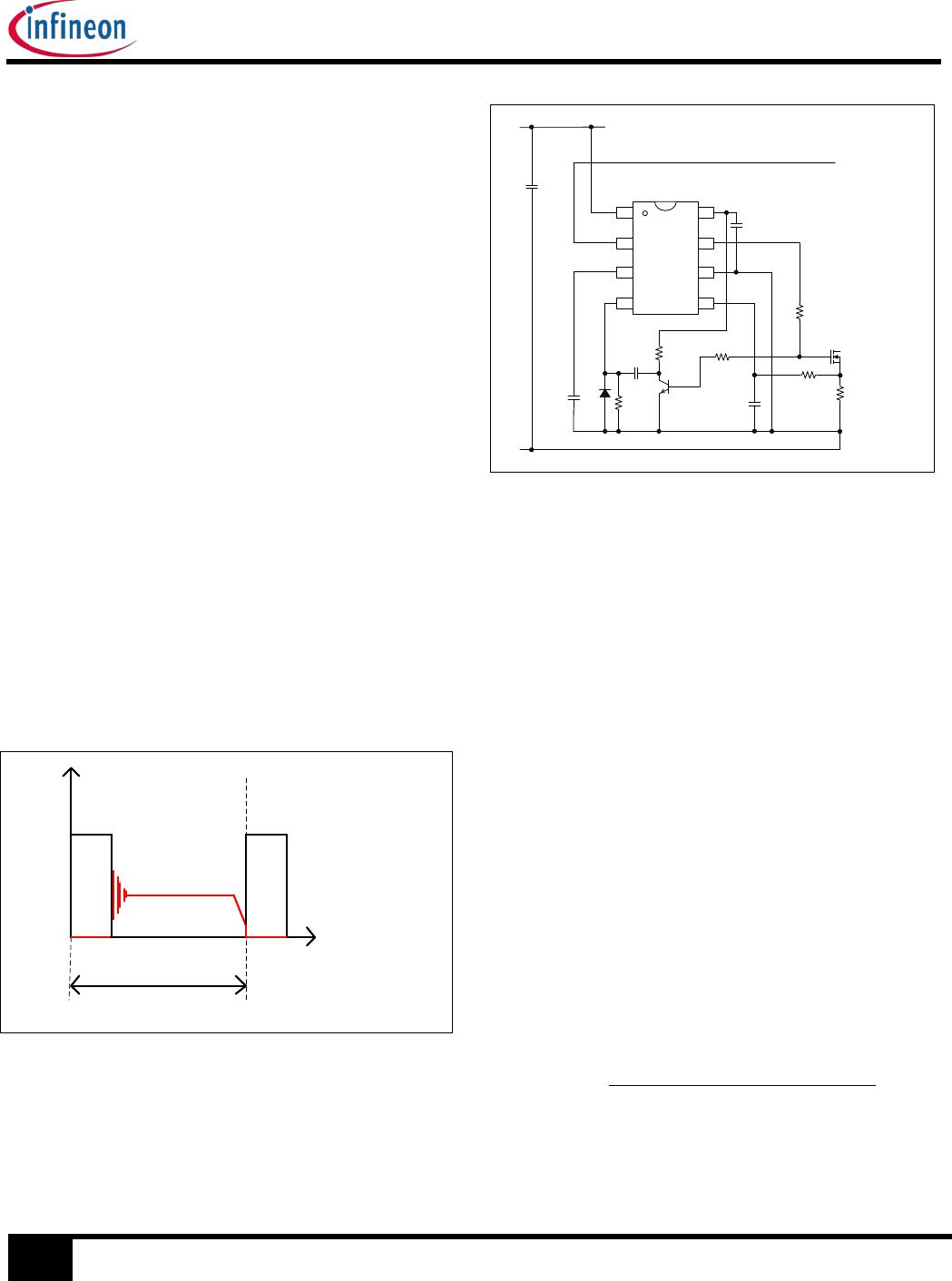
Voltage/current regulation
The IRS2982 may be operated using either a
voltage or current feedback loop. Examples of
each are shown above in the typical application
diagrams. The feedback voltage is fed to the FB
input of the IC, which is connected to the internal
transconductance error amplifier inverting input.
The non-inverting input is connected to an internal
temperature compensated band-gap voltage
reference (V
REF
) and the output is connected to the
compensation (COMP) output.
The FB input can be derived from a shunt resistor
returning LED load current to the 0V return in a
non-isolated Flyback LED driver to regulate output
current. Alternatively it can be fed by a divider
from the transformer auxiliary winding to provide
voltage regulation in an isolated power supply or a
divider directly from the output in a non-isolated
power supply. Sensing from the auxiliary winding
may require some additional filtering components
and does not provide highly accurate regulation of
the output voltage.
The compensation (COMP) voltage determines
the switching cycle on time for voltage mode
control. Loop compensation is performed by
means of the transconductance error amplifier
using an external capacitor (CCOMP) connected
to 0V to realize an integrator to provide a stable
error voltage used to control the converter on time.
CCOMP is typically 1μF in high power factor single
stage converters.
At light loads if V
COMP
drops below V
COMPOFF
the
IRS2982 operates in burst.
Burst mode operation
Under light load conditions the COMP capacitor is
discharged by the error amplifier reducing V
COMP
.
Minimum on time is reached just before V
COMP
falls
below V
COMPOFF
. If the output needs to be reduced
0
1
2
3
4
0 2 4 6 8 101214161820
HV startup current (mA)
VCC (V)
Startup
mode
Support
mode
IRS2982SPBF
14 2017-02-07
further then V
COMP
is driven below V
COMPOFF
and
the gate drive is disabled. However the HV start-
up cell does not switch from support to start-up
mode in this case.
Gate drive does not start up again until V
COMP
has
risen above this value by V
COMPOFF_HYS
at which
time it will start to switch at minimum on time.
During burst mode operation the on time typically
remains at minimum t
ONMIN
and the off time is
limited to the minimum off time t
OFFMIN
. Switching
frequency under these conditions is around
320kHz, which is the maximum possible for the
IRS2982. The length of each burst and the period
between bursts are determined by the value of
CCOMP in conjunction with the converter output
capacitor value.
The VCC supply is normally maintained through
the auxiliary winding, however if necessary the
high voltage regulator will supply current to VCC to
keep it just above V
CCUV-
.
t
tburst
V(t)
VOUT(t)
VCOMP(t)
Figure 2: Burst mode waveforms
Primary current limiting
Primary MOSFET current is sensed through a
shunt resistor (RCS) connected from the source of
the Flyback MOSFET switch to the DC bus return.
This current waveform is a high frequency ramp
rising from zero at the beginning of each switching
cycle to reach a peak level at the point the
MOSFET is switched off and remaining at zero
during the off time.
At very low input voltages the voltage or current
regulation loop would demand a very high peak
current, which may exceed the maximum rating of
the transformer. To prevent saturation from
occurring, the IRS2982 provides cycle by cycle
primary current limiting with a threshold V
CSTH
at
the CS pin input.
Under low line or fault conditions where the
MOSFET current is abnormally high the gate drive
is switched off after the blanking time t
BLANK
.
Leading edge blanking is necessary to avoid false
triggering due to the fast high current switch on
transient that occurs at switch on of the MOSFET
resulting from discharge of parasitic capacitances.
t
ts
V
(t
)
VOUT
(t
)
VCS(
t)
VCSTH
Figure 3: Cycle by cycle current limiting
The IRS2982 normally operates in critical
conduction mode (CrCM), also known as transition
or boundary mode. The transformer auxiliary
winding provides a signal to the IRS2982 ZX input
that indicates when all of the energy stored in the
inductor has been transferred to the output. This
triggers the start of the next switching cycle. The
auxiliary winding voltage is divided through RZX1
and RZX2 to provide the ZX pin input signal. The
pulse amplitude ZX is approximately proportional
to the secondary output voltage and therefore the
DC output voltage:
)21(
2
RZXRZXN
VOUTRZXN
VZX
S
A
+
[1]
Where,
N
A
= Number of turns on the auxiliary winding
N
S
= Number of turns on the secondary winding
VOUT = DC Output Voltage or LED voltage
In reality V
ZX
contains high frequency ringing
resulting from leakage inductance and other circuit
parasitics. This ringing may need to be filtered to
provide acceptable output voltage tracking.
When the converter MOSFET switches off, V
ZX
transitions positively. The values of RZX1 and
RZX2 must be selected so that this voltage always
IRS2982SPBF
15 2017-02-07
exceeds the V
ZX+
threshold to ensure CrCM
operation. If the IRS2982 is used in a converter
required to drive loads over a range of voltage
such as a constant current regulated LED driver,
V
ZX
needs to exceed V
ZX+
at the minimum load
voltage. If V
ZX
does not exceed V
ZX+
the IRS2982
will not operate in CrCM and remains pulsing with
the t
WD
timeout periodically triggering the next
cycle. In normal CrCM when V
ZX
exceeds V
ZX+
the
IRS2982 waits until the V
ZX
then drops below V
ZX-
again to initiate the next switching cycle. A
capacitor may be added in parallel with RZX2 to
add a small delay. This may be needed to
minimize switching loss by delaying switch on until
the minimum point or “valley” of the drain voltage.
The IRS2982 includes a minimum off time function
so that if the ZX pin input transitions high and low
in less than t
OFFMIN
, the gate drive output will not
transition high again until the end of this period.
This prevents false tripping by ringing at the ZX
input and also limits the converter maximum
switching frequency by entering DCM under
conditions where the off time would otherwise be
unacceptably short. The minimum off time extends
the operating range of the converter allowing
operation down to very low duty cycles. This
enables dimming designs to be implemented as
well as limiting operating frequency to limit
switching losses and prevent overheating of the
circuit magnetics, the MOSFET and snubber
components.
t
ts
V(t)
VOUT(t)
VZX(t)
Figure 4: Zero crossing detection
The IRS2982 may also be used in DCM by driving the
ZX input from a delay circuit triggered by the falling
edge of the gate drive output. A simple circuit is
added as shown in figure 5. As the gate drive goes
low a pulse of determined length can be generated to
drive ZX forcing the system to operate with a fixed off
time greater than the preset minimum off time.
CIN
MPFC
RPFC
RCS
CF
RF
IC1
CVCC
RZX
RC
RB
QZX
CC
DZXCCOMP
CS
COM
OUT
VCC
COMP
FB
HV
ZX
IRS2982
7
6
5
1
2
3
4
8
Figure 5: DCM Operation
Over voltage protection
The ZX input is a multi-function input also used for
output over voltage limiting. In a Flyback converter if
the load becomes disconnected the output voltage
can become very high causing rapid damage to
components as well as presenting a possible
electrical hazard. In order to protect against this the
IRS2982 senses the output voltage indirectly
through the ZX input, since its peak voltage tracks
the output voltage. If the ZX input voltage exceeds
V
OVTH
the gate drive switches off for a t
WD
period
before starting the next cycle. At the same time the
COMP capacitor is discharged below V
COMPOFF
so
after a delay the next cycle will begin at minimum
duty cycle and ramp up slowly. This protection
scheme allows the load to be hotconnected and
disconnected from the converter output without risk
of damaging the circuit by high voltages appearing
at the output. Care should be taken however to
avoid damage to LED loads due to output capacitor
discharge. An NTC thermistor at the output may be
needed to limit the current surge. The overvoltage
threshold is set by choosing the values of RZX1 and
RZX2 appropriately, according to the formula:
2
)21(
RZXN
RZXRZXN
VOVTH
VOUT
A
S
OV
+
[2]
The recommended over voltage threshold is 25%
above the normal operating voltage for LED loads.

IRS2982STRPBF

Mfr. #:
Manufacturer:
Infineon / IR
Description:
Display Drivers & Controllers CONTROLLER/GAN
Lifecycle:
New from this manufacturer.
Delivery:
DHL FedEx Ups TNT EMS
Payment:
T/T Paypal Visa MoneyGram Western Union

Products related to this Datasheet