ICS9DB803D
EIGHT OUTPUT DIFFERENTIAL BUFFER FOR PCIE GEN1 AND GEN2
IDT®
EIGHT OUTPUT DIFFERENTIAL BUFFER FOR PCIE GEN1 AND GEN2 4
ICS9DB803D REV N 071013
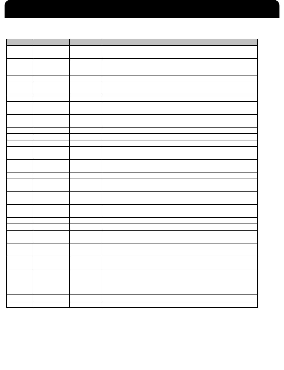
Pin Descriptions for OE_INV=0 (cont.)
PIN # PIN NAME PIN TYPE DESCRIPTION
25 GND PWR Ground pin.
26 PD# IN
Asynchronous active low input pin used to power down the
device. The internal clocks are disabled and the VCO and
the crystal osc. (if any) are stopped.
27 DIF_STOP# IN Active low input to stop differential output clocks.
28 HIGH_BW# PWR
3.3V input for selecting PLL Band Width
0 = High, 1= Low
29 DIF_4# OUT 0.7V differential Complementary clock output
30 DIF_4 OUT 0.7V differential true clock output
31 VDD PWR Power supply, nominal 3.3V
32 GND PWR Ground pin.
33 DIF_5# OUT 0.7V differential Complementary clock output
34 DIF_5 OUT 0.7V differential true clock output
35 OE_5 IN
Active high input for enabling output 5.
0 =disable outputs, 1= enable outputs
36 OE_6 IN
Active high input for enabling output 6.
0 =disable outputs, 1= enable outputs
37 DIF_6# OUT 0.7V differential Complementary clock output
38 DIF_6 OUT 0.7V differential true clock output
39 VDD PWR Power supply, nominal 3.3V
40 OE_INV IN
This latched input selects the polarity of the OE pins.
0 = OE pins active high, 1 = OE pins active low (OE#)
41 DIF_7# OUT 0.7V differential Complementary clock output
42 DIF_7 OUT 0.7V differential true clock output
43 OE_4 IN
Active high input for enabling output 4.
0 =disable outputs, 1= enable outputs
44 OE_7 IN
Active high input for enabling output 7.
0 =disable outputs, 1= enable outputs
45 LOCK OUT
3.3V output indicating PLL Lock Status. This pin goes high
when lock is achieved.
46 IREF IN
This pin establishes the reference for the differential current-
mode output pairs. It requires a fixed precision resistor to
ground. 475ohm is the standard value for 100ohm
differential impedance. Other impedances require different
values. See data sheet.
47 GNDA PWR Ground pin for the PLL core.
48 VDDA PWR 3.3V power for the PLL core.
ICS9DB803D
EIGHT OUTPUT DIFFERENTIAL BUFFER FOR PCIE GEN1 AND GEN2
IDT®
EIGHT OUTPUT DIFFERENTIAL BUFFER FOR PCIE GEN1 AND GEN2 5
ICS9DB803D REV N 071013
Pin Descriptions for OE_INV=1
PIN # PIN NAME PIN TYPE DESCRIPTION
1SRC_DIV# IN
Active low Input for determining SRC output frequency SRC or SRC/2.
0 = SRC/2, 1= SRC
2VDDR PWR
3.3V power for differential input clock (receiver). This VDD should be
treated as an analog power rail and filtered appropriately.
3 GND PWR Ground pin.
4 SRC_IN IN 0.7 V Differential SRC TRUE input
5 SRC_IN# IN 0.7 V Differential SRC COMPLEMENTARY input
6OE0# IN
Active low input for enabling DIF pair 0.
1 =disable outputs, 0 = enable outputs
7OE3# IN
Active low input for enabling DIF pair 3.
1 =disable outputs, 0 = enable outputs
8 DIF_0 OUT 0.7V differential true clock output
9 DIF_0# OUT 0.7V differential Complementary clock output
10 GND PWR Ground pin.
11 VDD PWR Power supply, nominal 3.3V
12 DIF_1 OUT 0.7V differential true clock output
13 DIF_1# OUT 0.7V differential Complementary clock output
14 OE1# IN
Active low input for enabling DIF pair 1.
1 =disable outputs, 0 = enable outputs
15 OE2# IN
Active low input for enabling DIF pair 2.
1 =disable outputs, 0 = enable outputs
16 DIF_2 OUT 0.7V differential true clock output
17 DIF_2# OUT 0.7V differential Complementary clock output
18 GND PWR Ground pin.
19 VDD PWR Power supply, nominal 3.3V
20 DIF_3 OUT 0.7V differential true clock output
21 DIF_3# OUT 0.7V differential Complementary clock output
22 BYPASS#/PLL IN
Input to select Bypass(fan-out) or PLL (ZDB) mode
0 = Bypass mode, 1= PLL mode
23 SCLK IN Clock pin of SMBus circuitry, 5V tolerant.
24 SDATA I/O Data pin for SMBus circuitry, 5V tolerant.
ICS9DB803D
EIGHT OUTPUT DIFFERENTIAL BUFFER FOR PCIE GEN1 AND GEN2
IDT®
EIGHT OUTPUT DIFFERENTIAL BUFFER FOR PCIE GEN1 AND GEN2 6
ICS9DB803D REV N 071013
Pin Descriptions for OE_INV=1 (cont.)
27 DIF_STOP
0 = High, 1= Lo
w
32 GND PWR Ground pin.
34 DIF_5 OUT 0.7V differential true clock output
1 =disable outputs, 0 = enable outputs
41 DIF_7# OUT 0.7V differential Complementary clock output
output pairs. It requires a fixed precision resistor to ground. 475ohm is
47 GNDA PWR Ground pin for the PLL core.

9DB803DGILFT

Mfr. #:
Manufacturer:
IDT
Description:
Clock Buffer 8 OUTPUT PCIE GEN2 BUFFER
Lifecycle:
New from this manufacturer.
Delivery:
DHL FedEx Ups TNT EMS
Payment:
T/T Paypal Visa MoneyGram Western Union