BGA6589 All information provided in this document is subject to legal disclaimers. © NXP B.V. 2011. All rights reserved.
Product data sheet Rev. 3 — 28 November 2011 8 of 14
NXP Semiconductors
BGA6589
MMIC wideband medium power amplifier
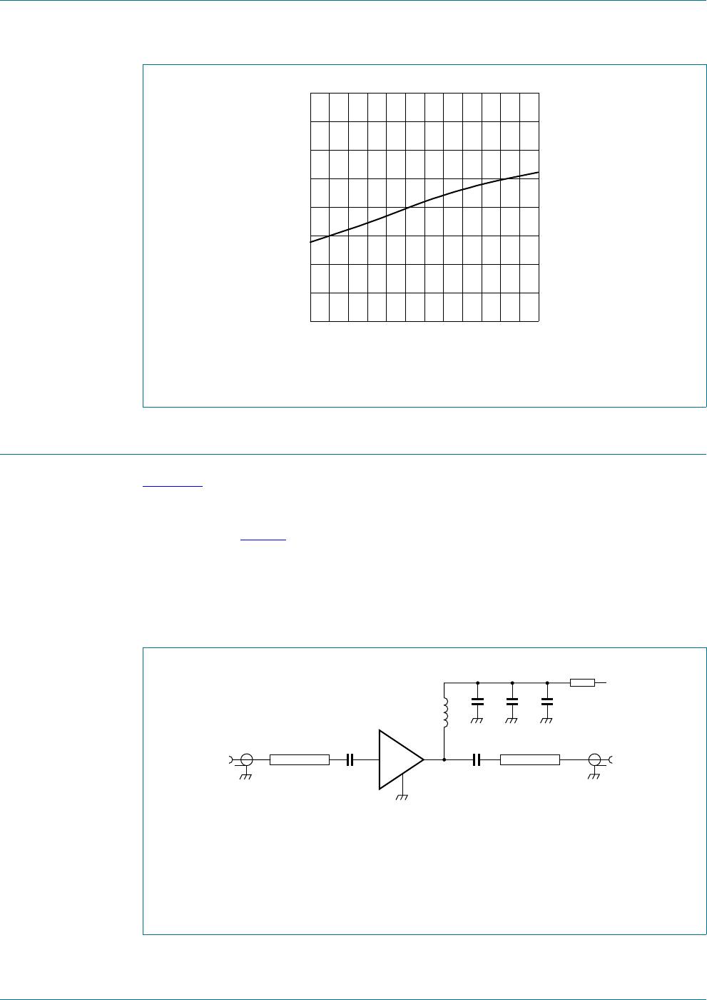
[1] Optional.
Table 9. List of components
See Figure 10 for circuit.
Component Description Type Value at operating frequency
500 MHz 800 MHz 1950 MHz 2400 MHz 3500 MHz
C1, C2 multilayer ceramic chip
capacitor
0603 220 pF 100 pF 68 pF 56 pF 39 pF
C3 multilayer ceramic chip
capacitor
0603 100 pF 68 pF 22 pF 22 pF 15 pF
C4 multilayer ceramic chip
capacitor
0603 1 nF 1 nF 1 nF 1 nF 1 nF
C5
[1]
electrolytic or tantalum
capacitor
0603 1 F1 F1 F1 F1 F
L1 SMD inductor 0603 68 nH 33 nH 22 nH 18 nH 15 nH
R1 SMD resistor, 0.5 W;
V
S
=9V
- 51 51 51 51 51
Table 10. Scattering parameters
I
S
= 81 mA; V
S
=9V; P
D
=
30 dBm; Z
O
=50
; T
amb
=25
C.
f (MHz) s
11
s
21
s
12
s
22
K factor
Magnitude
(ratio)
Angle
(degree)
Magnitude
(ratio)
Angle
(degree)
Magnitude
(ratio)
Angle
(degree)
Magnitude
(ratio)
Angle
(degree)
200 0.30 6.87 16.61 161.86 0.04 2.38 0.34 20.03 1.0
300 0.31 10.91 16.18 153.02 0.04 3.66 0.34 30.50 1.0
400 0.32 15.72 15.59 144.39 0.04 5.17 0.34 40.74 1.1
500 0.33 21.0 14.91 136.01 0.04 6.75 0.34 50.56 1.1
600 0.33 26.44 14.19 128.12 0.04 8.67 0.34 60.07 1.1
700 0.34 32.08 13.51 120.88 0.04 10.94 0.33 69.21 1.1
800 0.34 37.75 12.77 114.19 0.04 13.65 0.33 77.91 1.1
900 0.35 43.18 11.88 107.40 0.04 15.15 0.32 86.13 1.1
1000 0.35 48.9 11.22 101.34 0.04 17.89 0.32 94.01 1.1
1100 0.35 54.2 10.64 95.86 0.04 19.93 0.31 101.7 1.1
1200 0.35 59.55 10.0 90.82 0.05 22.11 0.30 109.1 1.1
1300 0.34 64.78 9.39 85.46 0.05 24.10 0.30 116.4 1.1
1400 0.34 69.93 8.93 80.15 0.05 24.62 0.29 123.6 1.1
1500 0.33 74.81 8.54 75.95 0.05 25.98 0.28 130.9 1.1
1600 0.33 79.82 8.07 72.26 0.05 27.67 0.27 138.2 1.1
1700 0.32 84.88 7.60 67.95 0.06 28.69 0.26 145.7 1.1
1800 0.31 89.81 7.32 63.43 0.06 28.33 0.25 153.6 1.1
1900 0.30 94.89 7.08 59.81 0.06 28.44 0.24 162.0 1.1
2000 0.29 100.3 6.74 56.09 0.07 29.27 0.23 170.7 1.1
2100 0.28 105.9 6.46 51.84 0.07 29.17 0.23 179.99 1.1
2200 0.26
111.8 6.28 48.02 0.07 28.46 0.22 170.17 1.2
2
300 0.25 118.0 6.07 45.0 0.08 28.37 0.22 160.16 1.2
2400 0.24 125.2 5.78 41.33 0.08 28.17 0.22 149.59 1.1