LTC2942-1
15
29421f
Information furnished by Linear Technology Corporation is believed to be accurate and reliable.
However, no responsibility is assumed for its use. Linear Technology Corporation makes no representa-
tion that the interconnection of its circuits as described herein will not infringe on existing patent rights.
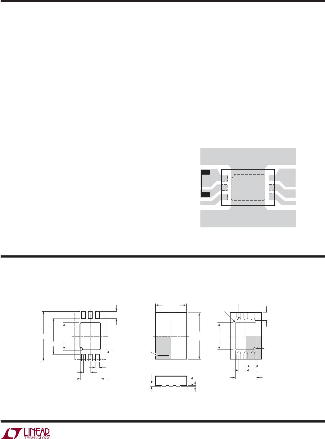
package DescripTion
Figure 11. Recommended Layout
DCB Package
6-Lead Plastic DFN (2mm × 3mm)
(Reference LTC DWG # 05-08-1715)
3.00 p0.10
(2 SIDES)
2.00 p0.10
(2 SIDES)
NOTE:
1. DRAWING TO BE MADE A JEDEC PACKAGE OUTLINE M0-229 VARIATION OF (TBD)
2. DRAWING NOT TO SCALE
3. ALL DIMENSIONS ARE IN MILLIMETERS
4. DIMENSIONS OF EXPOSED PAD ON BOTTOM OF PACKAGE DO NOT INCLUDE
MOLD FLASH. MOLD FLASH, IF PRESENT, SHALL NOT EXCEED 0.15mm ON ANY SIDE
5. EXPOSED PAD SHALL BE SOLDER PLATED
6. SHADED AREA IS ONLY A REFERENCE FOR PIN 1 LOCATION ON THE
TOP AND BOTTOM OF PACKAGE
0.40 p 0.10
BOTTOM VIEW—EXPOSED PAD
1.65 p 0.10
(2 SIDES)
0.75 p0.05
R = 0.115
TYP
R = 0.05
TYP
1.35 p0.10
(2 SIDES)
1
3
64
PIN 1 BAR
TOP MARK
(SEE NOTE 6)
0.200 REF
0.00 – 0.05
(DCB6) DFN 0405
0.25 p 0.05
0.50 BSC
PIN 1 NOTCH
R0.20 OR 0.25
s 45o CHAMFER
0.25 p 0.05
1.35 p0.05
(2 SIDES)
RECOMMENDED SOLDER PAD PITCH AND DIMENSIONS
1.65 p0.05
(2 SIDES)
2.15 p0.05
0.70 p0.05
3.55 p0.05
PACKAGE
OUTLINE
0.50 BSC
Measuring Current
In some applications, it may be desirable to measure the
current I
SENSE
flowing through the internal sense resistor.
Since charge measured by the coulomb counter is the
time integral over I
SENSE
, differentiation of the contents
of the accumulated charge register (ACR) over time may
be used to measure average current.
Accuracy of such an indirect current measurement is limited
by the basic accuracy of the coulomb counter, the accuracy
of the timebase within the host system, quantization caused
by the prescaler setting, and time delays caused by I
2
C
transactions. Still, especially at higher currents, useful
results may be obtained by reading the accumulated charge
register twice, with a defined time interval in between, and
dividing the charge difference by the time interval. The
time interval may be increased at low currents to limit time
quantization errors to the desired accuracy. For quicker
current measurements at low currents, prescale factor M
may be temporarily decreased, sacrificing some coulomb
count accuracy for higher current resolution.
Extending Coulomb Counter Range
To increase the range of the coulomb counter for battery
capacities higher than 5.5Ah, the host controller can either
regularly poll the accumulated charge register (ACR) or use
the threshold registers to determine when the accumulated
charge register approaches the minimum or maximum
limits. At this point it can add or subtract a fixed charge
quantity and rewrite the result into the ACR. The added
or subtracted charge quantities can then be tracked in
software, increasing the effective ACR range.
PC Board Layout Suggestions
Keep all traces as short as possible to minimize noise and
inaccuracy. Use wider traces from the resistor to the bat-
tery, load and/or charger (see Figure 11). Put the bypass
capacitor close to SENSE
+
and GND. Provide adequate
copper area on exposed pad for heat sinking.
LTC2942-1
ELECTRICALLY ISOLATED HEAT SINK
CONNECTED TO EXPOSED PAD ONLY
29421 F11
TO BATTERY
TO
CHARGER/LOAD
4
5
6
3
2
1
C
applicaTions inFormaTion