LTC2942-1
4
29421f
Timing Diagram
t
SU, DAT
t
SU, STO
t
SU, STA
t
BUF
t
HD, STA
t
HD, DATO,
t
HD, DATI
t
HD, STA
START
CONDITION
STOP
CONDITION
REPEATED START
CONDITION
START
CONDITION
SDA
SCL
29421 F01
t
of
Figure 1. Definition of Timing on I
2
C Bus
elecTrical characTerisTics
The l denotes the specifications which apply over the full operating
temperature range, otherwise specifications are at T
A
= 25°C. (Note 2)
SYMBOL PARAMETER CONDITIONS MIN TYP MAX UNITS
t
HD,DATI(MIN)
Minimum Data Hold Time Input
l
0 µs
t
HD,DATO
Data Hold Time Output
l
0.3 0.9 µs
t
of
Data Output Fall Time (Notes 7, 8)
l
20 + 0.1 • C
B
300 ns
Note 1: Stresses beyond those listed under Absolute Maximum Ratings
may cause permanent damage to the device. Exposure to any Absolute
Maximum Rating condition for extended periods may affect device
reliability and lifetime.
Note 2: All currents into pins are positive, all voltages are referenced to
GND unless otherwise specified
Note 3: I
SUPPLY
= I
SENSE
+
+ I
SENSE
Note 4: The equivalent charge of an LSB in the accumulated charge
register depends on the setting of the internal prescaling factor M:
q
LSB
= 0.085mAh
M
128
See Choosing Coulomb Counter Prescaler M section for more information.
1mAh = 3.6C (Coulombs).
Note 5: Deviation of q
LSB
from its nominal value. Data is for a new device
and does not include long-term sense resistor aging. See the Internal
Sense Resistor section for more information.
Note 6: The quantization step of the 14-bit ADC in voltage mode and
10-bit ADC in temperature mode is not to be mistaken with the LSB of the
combined 16-bit voltage registers (I, J) and 16-bit temperature registers
(M, N).
Note 7: C
B
= Capacitance of one bus line in pF (10pF ≤ C
B
≤ 400pF). See
Voltage and Temperature Registers section for more information.
Note 8: Guaranteed by design, not subject to test.
Note 9: Value decreases if exposed pad is soldered to large copper area.
See Power Dissipation section for more information.
Note 10: Use for scaling of temperature reading only. Do not use part
outside operating temperature range.
LTC2942-1
5
29421f
Typical perFormance characTerisTics
Supply Current vs Supply Voltage
Shutdown Supply Current
vs Supply Voltage
Voltage Measurement ADC
Total Unadjusted Error
Temperature Error vs Temperature
Total Charge Error
vs Sense Current
Total Charge Error
vs Supply Voltage Total Charge Error vs Temperature
|I
SENSE
| (mA)
1
–0.50
CHARGE ERROR (%)
0
–0.25
–0.75
0.25
0.50
10 100 1000
29421 G01
–1.00
1.00
0.75
V
SENSE
+ = 2.7V
V
SENSE
+ = 4.2V
V
SENSE
+
(V)
2.5
–1.0
CHARGE ERROR (%)
–0.8
–0.4
–0.2
0
1.0
0.4
3.5
4.5
5
29421 G02
–0.6
0.6
0.8
0.2
3
4
5.5
6
|I
SENSE
| = 1A
|I
SENSE
| = 200mA
V
SENSE
+
(V)
2.5
I
SUPPLY
(µA)
80
90
100
4.0 5.0
29421 G04
70
60
3.0 3.5
4.5 5.5 6.0
50
40
T
A
= 25°C
T
A
= –40°C
T
A
= 85°C
V
SENSE
+
(V)
2.5
0
I
SHUTDOWN
(µA)
1.0
2.0
3.5
4.5
5.0
29421 G05
0.5
1.5
3.0
4.0
5.5
6.0
T
A
= 25°C
T
A
= –40°C
T
A
= 85°C
Voltage Measurement ADC
Integral Nonlinearity
TEMPERATURE (°C)
–50 –25
–3
TEMPERATURE ERROR (°C)
–2
–1
0
1
2
3
0 755025 100
29421 G08
V
SENSE
(V)
2.5
–10
TOTAL UNADJUSTED ERROR (mV)
–8
–4
–2
0
10
4
3.5
4.5
5.0
29421 G06
–6
6
8
2
3.0
4.0
5.5
6.0
T
A
= 25°C
T
A
= 85°C
T
A
= –45°C
V
SENSE
(V)
2.5
INL (V
LSB
)
4.0
29421 G07
0
–1.0
3.0 3.5 4.5
1.0
0.5
–0.5
5.0 5.5 6.0
T
A
= –40°C
T
A
= 85°C
T
A
= 25°C
Sense Resistor Stability
kHOURS
–3.0
∆R/R
O
(%)
–2.0
–1.0
0
–2.5
–1.5
–0.5
10 20 30 40
29421 G09
500
ACCELERATED LOAD LIFE TEST
DATA SCALED TO T
AMB
= 85°C,
I
SENSE
= 1A CONDITIONS
LTC2942-1
6
29421f
pin FuncTions
block Diagram
SENSE
+
(Pin 1): Positive Current Sense Input and Power
Supply. Connect to the load and battery charger output.
V
SENSE
+
operating range is 2.7V to 5.5V.
GND (Pin 2): Device Ground. Connect directly to the nega-
tive battery terminal.
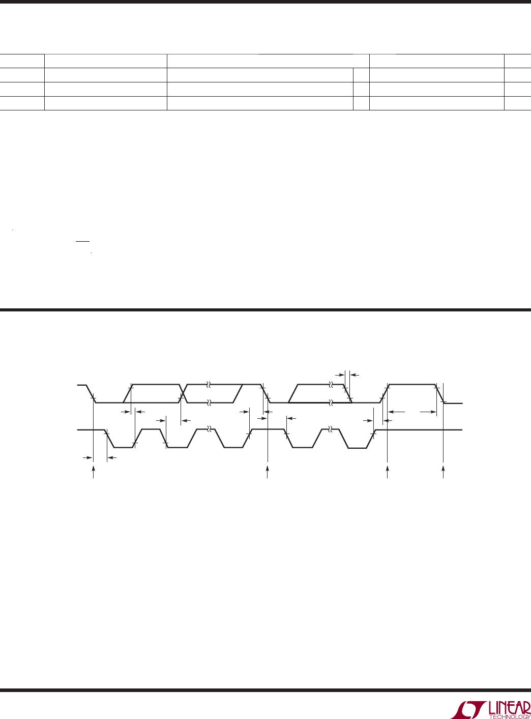
SCL (Pin 3): Serial Bus Clock Input.
SDA (Pin 4): Serial Bus Data Input and Output.
AL/CC (Pin 5): Alert Output or Charge Complete Input.
Configured either as an SMBus alert output or charge
complete input by control register bits B[2:1]. At power-up,
the pin defaults to alert mode conforming to the SMBus
alert response protocol. It behaves as an open-drain logic
output that pulls to GND when any threshold register value
is exceeded. When configured as a charge complete input,
a high level at CC sets the value of the accumulated charge
(registers C, D) to FFFFh. Columb counting starts when
the input returns to low level.
SENSE
(Pin 6): Negative Current Sense Input. Connect
SENSE
to the positive battery terminal. Current from/into
this pin must not exceed 1A in normal operation.
Exposed Pad (Pin 7): Do Not Connect. Soldering the
exposed pad to adequate electrically isolated copper area
is recommended for best thermal performance, and best
accuracy of the integrated temperature sensor.
REF
+
REF
REF CLK
COULOMB COUNTER
ADC
IN
CLK
MUX
SENSE
REFERENCE
GENERATOR
TEMPERATURE
SENSOR
ACCUMULATED
CHARGE
REGISTER
DATA AND
CONTROL
REGISTERS
OSCILLATOR
6
SENSE
+
1
AL/CC
AL
5
GND
R
SENSE
50
2
I
2
C/
SMBus
SCL
CC
SDA
29421 BD
3
4
V
SUPPLY
R
BOND
12
R
BOND
12
operaTion
Overview
The LTC2942-1 is a battery gas gauge device designed
for use with single Li-Ion cells and other battery types
with terminal voltages from 2.7V to 5.5V. It measures
battery charge and discharge, battery voltage and chip
temperature. A precision coulomb counter integrates
current through an internal sense resistor between the
batterys positive terminal and the load or charger. Battery
voltage and on-chip temperature are measured with an
internal 14-bit/10-bit ADC. The integrated, temperature-
compensated sense resistor offers board space savings
and superior charge measurement accuracy in applications
with currents up to 1A.

LTC2942IDCB-1#TRPBF

Mfr. #:
Manufacturer:
Analog Devices / Linear Technology
Description:
Battery Management Battery Gas Gauge with Temperature & Voltage Measurement and Internal Sense Resistor
Lifecycle:
New from this manufacturer.
Delivery:
DHL FedEx Ups TNT EMS
Payment:
T/T Paypal Visa MoneyGram Western Union