LTC2942-1
7
29421f
Coulomb Counter
Charge is the time integral of current. The LTC2942-1 mea-
sures battery current by monitoring the voltage developed
across its internal sense resistor and then integrates this
information to infer charge. The internal sense resistor is
tied between the SENSE
+
and SENSE
pins and is con-
nected to an auto-zeroed differential analog integrator
which converts the measured current to charge.
When the integrator output reaches the REFHI or REFLO
thresholds, switches S1, S2, S3 and S4 toggle to reverse
the ramp direction. By observing the condition of the
switches and the ramp direction, polarity is determined. A
programmable prescaler effectively increases integration
time by a factor M programmable from 1 to 128. At each
underflow or overflow of the prescaler, the accumulated
charge register (ACR) value is incremented or decremented
one count. The value of accumulated charge is read via
the I
2
C interface.
Voltage and Temperature ADC
The LTC2942-1 includes a 14-bit No Latency ∆Σ analog-
to-digital converter, with internal clock and voltage refer-
ence circuits.
+
LOADCHARGER
R
SENSE
BATTERY
I
BAT
+
+
+
S4
R
BOND
R
BOND
REFHI
REFLO
S3
S2
S1
V
CC
SENSE
+
1
SENSE
6
GND
2
POLARITY
DETECTION
CONTROL
LOGIC
M
PRESCALER
ACR
29421 F02
Figure 2. Coulomb Counter Section of the LTC2942-1
The ADC can either be used to monitor the battery voltage
at SENSE
or to convert the output of the on-chip tempera-
ture sensor. The sensor generates a voltage proportional to
temperature with a slope of 2.5mV/K resulting in a voltage
of 750mV at 27°C.
Conversion of either temperature or voltage is triggered
by setting the control register via the I
2
C interface. The
LTC2942-1 features an automatic mode where a voltage
and a temperature conversion are executed every two
seconds. At the end of each conversion the corresponding
registers are updated and the converter goes to sleep to
minimize quiescent current.
Power-Up Sequence
When V
SENSE
+ rises above a threshold of approximately
2.5V, the LTC2942-1 generates an internal power-on reset
(POR) signal and sets all registers to their default state.
In the default state, the coulomb counter is active while
the voltage and temperature ADC is switched off. The
accumulated charge register is set to mid-scale (7FFFh),
all low threshold registers are set to 0000h and all high
threshold registers are set to FFFFh. The alert mode is
enabled and the coulomb counter pre-scaling factor M
is set to 128.
operaTion
LTC2942-1
8
29421f
applicaTions inFormaTion
I
2
C/SMBus Interface
The LTC2942-1 communicates with a bus master using a
2-wire interface compatible with I
2
C and SMBus. The 7-bit
hard-coded I
2
C address of the LTC2942-1 is 1100100.
The LTC2942-1 is a slave-only device. Therefore the serial
clock line (SCL) is an input only while the serial data line
(SDA) is bidirectional. The device supports I
2
C standard
and fast mode. For more details refer to the I
2
C Protocol
section.
Internal Registers
The LTC2942-1 integrates current through a sense resistor,
measures battery voltage and temperature and stores the
results in internal 16-bit registers accessible via I
2
C. High
and low limits can be programmed for each measurement
quantity. The LTC2942-1 continuously monitors these
limits and sets a corresponding flag in its status register
when a limit is exceeded. If the alert mode is enabled, the
AL/CC pin pulls low.
The sixteen internal registers are organized as shown in
Table 1.
Table 1. Register Map
ADDRESS NAME REGISTER DESCRIPTION R/W DEFAULT
00h A Status R See Below
01h B Control R/W 3Ch
02h C Accumulated Charge MSB R/W 7Fh
03h D Accumulated Charge LSB R/W FFh
04h E Charge Threshold High MSB R/W FFh
05h F Charge Threshold High LSB R/W FFh
06h G Charge Threshold Low MSB R/W 00h
07h H Charge Threshold Low LSB R/W 00h
08h I Voltage MSB R XXh
09h J Voltage LSB R XXh
0Ah K Voltage Threshold High R/W FFh
0Bh L Voltage Threshold Low R/W 00h
0Ch M Temperature MSB R XXh
0Dh N Temperature LSB R XXh
0Eh O Temperature Threshold High R/W FFh
0Fh P Temperature Threshold Low R/W 00h
R = Read, W = Write, XX = unknown
Status Register (A)
The status of the charge, voltage and temperature alerts
is reported in the status register shown in Table 2.
Table 2. Status Register A (Read only)
BIT NAME OPERATION DEFAULT
A[7] Chip Identification 0: LTC2942-1
1: LTC2941-1
0
A[6] Reserved Not Used. 0
A[5] Accumulated Charge
Overflow/Underflow
Indicates that the value of the
accumulated charge hit either
top or bottom.
0
A[4] Temperature Alert Indicates one of the
temperature limits was
exceeded.
0
A[3] Charge Alert High Indicates that the accumulated
charge value exceeded the
charge threshold high limit.
0
A[2] Charge Alert Low Indicates that the accumulated
charge value dropped below
the charge threshold low limit.
0
A[1] Voltage Alert Indicates one of the battery
voltage limits was exceeded.
0
A[0] Undervoltage
Lockout Alert
Indicates recovery from
undervoltage. If set to 1, a
UVLO has occurred and the
content of the registers is
uncertain.
X
All status register bits except A[7] are cleared after being
read by the host, if the conditions which set these bits
have been removed.
As soon as one of the three measured quantities exceeds
the programmed limits, the corresponding bit A[4], A[3],
A[2] or A[1] in the status register is set.
Bit A[5] is set if the LTC2942-1’s accumulated charge
registers (ACR) overflows or underflows. In these cases,
the ACR stays at FFFFh or 0000h and does not roll over.
The undervoltage lockout (UVLO) bit of the status register
A[0] is set if, during operation, the voltage on SENSE
+
pin drops below 2.7V without reaching the POR level.
The analog parts of the coulomb counter are switched off
while the digital register values are retained. After recov-
ery of the supply voltage the coulomb counter resumes
integrating with the stored value in the accumulated
charge registers but it has missed any charge flowing
while SENSE
+
< 2.7V.
LTC2942-1
9
29421f
applicaTions inFormaTion
The hard-coded bit A[7] of the status register enables the
host to distinguish the LTC2942-1 from the pin compat-
ible LTC2941, allowing the same software to be used with
both devices.
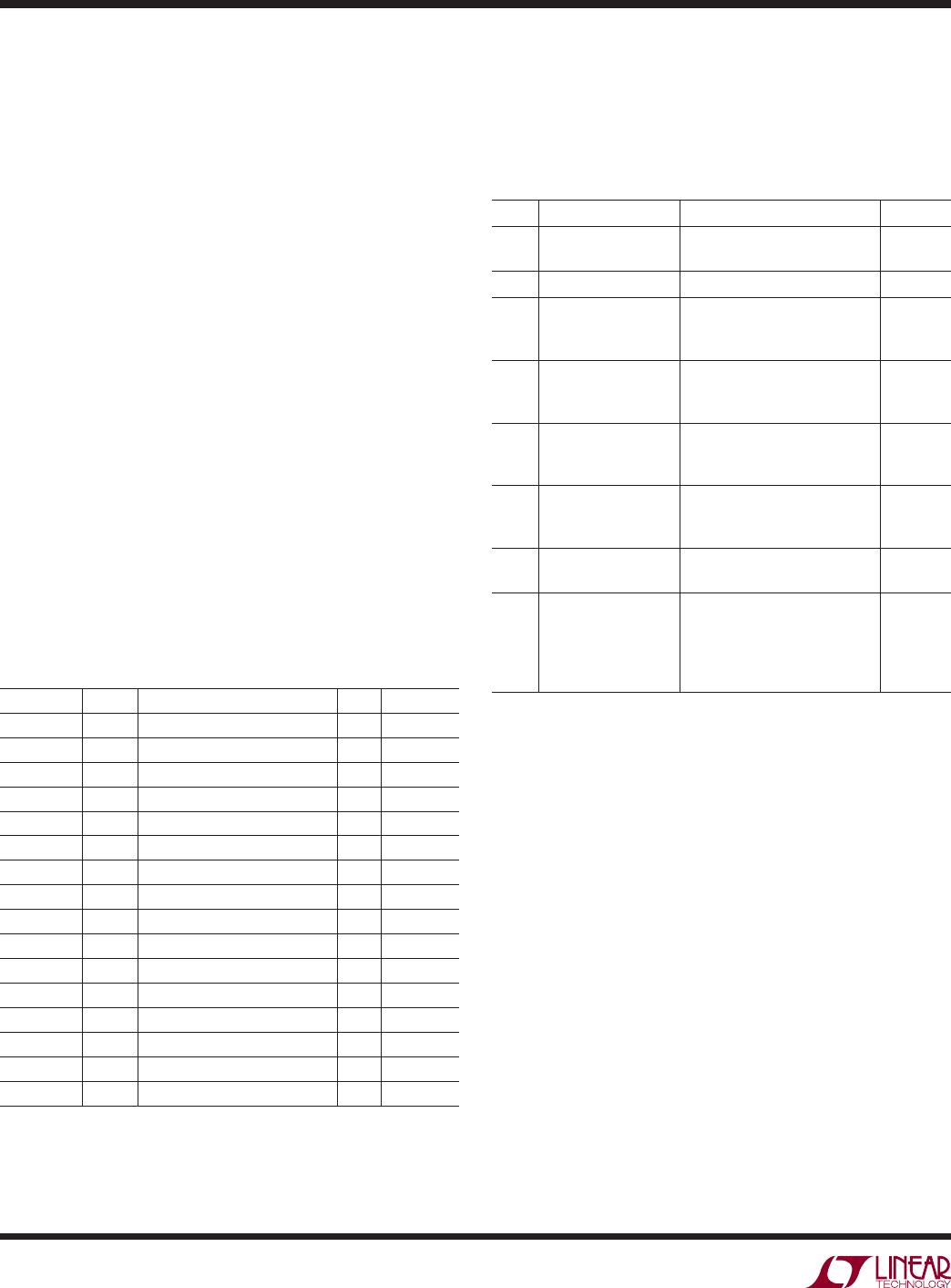
Control Register (B)
The operation of the LTC2942-1 is controlled by program-
ming the control register. Table 3 shows the organization
of the 8-bit control register B[7:0].
Table 3. Control Register B
BIT NAME OPERATION Default
B[7:6] ADC Mode [11] Automatic Mode.
Performs voltage and temperature
conversion every second.
[10] Manual Voltage Mode.
Performs single voltage
conversion, then sleeps.
[01] Manual Temperature Mode.
Performs single temperature
conversion, then sleeps.
[00] Sleep.
[00]
B[5:3] Prescaler M Sets coulomb counter prescaling
factor M between 1 and 128.
Default is 128.
M = 2
(4 • B[5] + 2 • B[4] + B[3])
[111]
B[2:1] AL/CC Configure Configures the AL/CC pin.
[10] Alert Mode.
Alert functionality enabled.
Pin becomes logic output.
[01] Charge Complete Mode.
Pin becomes logic input and
accepts “charge complete” signal
(e.g., from a charger) to set
accumulated charge register (C,D)
to FFFFh.
[00] AL/CC pin disabled.
[11] Not allowed.
[10]
B[0] Shutdown Shut down analog section to
reduce I
SUPPLY
.
[0]
Power Down B[0]
Programming the last bit B[0] of the control register to 1
sets the analog parts of the LTC2942-1 in power down and
the current consumption drops typically below 1µA. All
analog circuits are disabled while the values in the registers
are retained. Note that any charge flowing while B[0] is 1
is not measured and the charge information below 1LSB
of the accumulated charge register is lost.
Alert/Charge Complete Configuration B[2:1]
The AL/CC pin is a dual function pin configured by the
control register. By setting bits B[2:1] to [10] (default)
the AL/CC pin is configured as an alert pin following the
SMBus protocol. In this configuration the AL/CC pin is a
digital output and is pulled low if one of the three mea-
sured quantities (charge, voltage, temperature) exceeds
its high or low threshold or if the value of the accumulated
charge register overflows or underflows. An alert response
procedure started by the master resets the alert at the
AL/CC pin. For further information see the Alert Response
Protocol section.
Setting the control bits B[2:1] to [01] configures the AL/CC
pin as a digital input. In this mode, a high input on the
AL/CC pin communicates to the LTC2942-1 that the bat-
tery is full and the accumulated charge register is set to
its maximum value FFFFh. Columb counting starts when
the AL/CC pin returns to low level.
If neither the alert nor the charge complete functionality
is desired, bits B[2:1] should be set to [00]. The AL/CC
pin is then disabled and should be tied to GND.
Avoid setting B[2:1] to [11] as it enables the alert and the
charge complete modes simultaneously.
Choosing Coulomb Counter Prescaler ‘M’ B[5:3]
To use as much of the range of the accumulated charge
register as possible the prescaler factor M is chosen based
on battery capacity Q
BAT
:
M
Q
mAh
Ah
Q
BAT
BAT
=128
2 0 085
23
16
.
M can be set to 1, 2, 4, 8,... 128 by programming B[5:3] of
the control register as M = 2
(4 B[5] + 2 B[4] + B[3])
. The default
value after power up is M = 128 = 2
7
(B[5:3] = 111). The
maximum battery capacity supported within the prescaler
range is 5.5Ah with M = 128. See the section Extending
Coulomb Counter Range if battery capacity is higher.
Depending on the choice of prescaler factor M, the charge
LSB of the accumulated charge register becomes:
q mAh
M
LSB
= 0 085
128
.

LTC2942IDCB-1#TRPBF

Mfr. #:
Manufacturer:
Analog Devices / Linear Technology
Description:
Battery Management Battery Gas Gauge with Temperature & Voltage Measurement and Internal Sense Resistor
Lifecycle:
New from this manufacturer.
Delivery:
DHL FedEx Ups TNT EMS
Payment:
T/T Paypal Visa MoneyGram Western Union