MPX5700
Rev 10, 10/2012
Freescale Semiconductor
Data Sheet: Technical Data
© 2007-2009, 2012 Freescale Semiconductor, Inc. All rights reserved.
Pressure
Integrated Silicon Pressure Sensor
On-Chip Signal Conditioned,
Temperature Compensated and
Calibrated
The MPX5700 series piezoresistive transducer is a state-of-the-art
monolithic silicon pressure sensor designed for a wide range of applications,
but particularly those employing a microcontroller or microprocessor with A/D
inputs. This patented, single element transducer combines advanced
micromachining techniques, thin-film metallization, and bipolar processing to
provide an accurate, high level analog output signal that is proportional to the
applied pressure.
Features
2.5% Maximum Error over 0 to 85C
Ideally Suited for Microprocessor or Microcontroller-Based Systems
Available in Absolute, Differential and Gauge Configurations
Patented Silicon Shear Stress Strain Gauge
Durable Epoxy Unibody Element
ORDERING INFORMATION
Device Name
Case
No.
# of Ports Pressure Type
Device
Name
None Single Dual Gauge Differential Absolute
Unibody Package (MPX5700 Series)
MPX5700A
867 MPX5700A
MPX5700AP
867B MPX5700AP
MPX5700AS
867E MPX5700A
MPX5700ASX
867F MPX5700A
MPX5700D
867 MPX5700D
MPX5700DP
867C MPX5700DP
MPX5700GP
867B MPX5700GP
MPX5700GP1
(1)
1. MPX5700GP1 has 90 degree lead form.
867B MPX5700GP
MPX5700GS
867E MPX5700D
MPX5700
Series
0 to 700 kPa (0 to 101.5 psi)
15 to 700 kPa (2.18 to 101.5 psi)
0.2 to 4.7 V Output
MPX5700A/D
CASE 867-08
MPX5700AP/GP/GP1
CASE 867B-04
MPX5700DP
CASE 867C-05
MPX5700AS/GS
CASE 867E-03
MPX5700ASX
CASE 867F-03
UNIBODY PACKAGES
MPX5700
Sensors
2 Freescale Semiconductor, Inc.
Pressure
Operating Characteristics
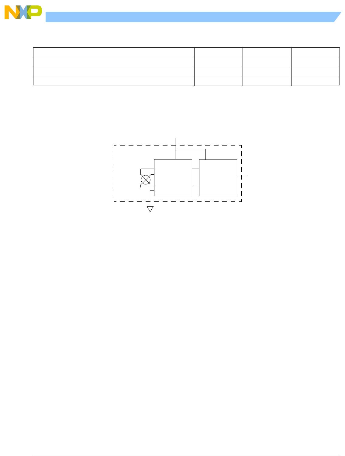
Table 1. Operating Characteristics (V
S
= 5.0 Vdc, T
A
= 25°C unless otherwise noted, P1 > P2. Decoupling circuit shown in
required to meet electrical specifications.)
Characteristic Symbol Min Typ Max Unit
Pressure Range
(1)
Gauge, Differential: MPX5700D
Absolute: MPX5700A
1. 1.0 kPa (kiloPascal) equals 0.145 psi.
P
OP
0
15
700
700
kPa
Supply Voltage
(2)
2. Device is ratiometric within this specified excitation range.
V
S
4.75 5.0 5.25 Vdc
Supply Current I
O
—7.010mAdc
Zero Pressure Offset
(3)
Gauge, Differential (0 to 85C)
Absolute (0 to 85C)
3. Offset (V
off
) is defined as the output voltage at the minimum rated pressure.
V
off
0.088
0.184
0.2
0.313
0.409
Vdc
Full Scale Output
(4)
(0 to 85C)
4. Full Scale Output (V
FSO
) is defined as the output voltage at the maximum or full rated pressure.
V
FSO
4.587 4.7 4.813 Vdc
Full Scale Span
(5)
(0 to 85C)
5. Full Scale Span (V
FSS
) is defined as the algebraic difference between the output voltage at full rated pressure and the output voltage at the
minimum rated pressure.
V
FSS
—4.5—Vdc
Accuracy
(6)
(0 to 85C)
6. Accuracy (error budget) consists of the following:
Linearity: Output deviation from a straight line relationship with pressure over the specified pressure range.
Temperature Hysteresis: Output deviation at any temperature within the operating temperature range, after the temperature is cycled to and
from the minimum or maximum operating temperature points, with zero differential pressure applied.
Pressure Hysteresis: Output deviation at any pressure within the specified range, when this pressure is cycled to and from the minimum or
maximum rated pressure, at 25°C.
TcSpan: Output deviation over the temperature range of 0° to 85°C, relative to 25°C.
TcOffset: Output deviation with minimum rated pressure applied, over the temperature range of 0° to 85°C, relative to 25°C.
Variation from Nominal: The variation from nominal values, for Offset or Full Scale Span, as a percent of V
FSS
, at 25°C.
———2.5 %V
FSS
Sensitivity V/P 6.4 mV/kPa
Response Time
(7)
7. Response Time is defined as the time for the incremental change in the output to go from 10% to 90% of its final value when subjected to a
specified step change in pressure.
t
R
—1.0—ms
Output Source Current at Full Scale Output I
O+
—0.1—mAdc
Warm-Up Time
(8)
8. Warm-up Time is defined as the time required for the device to meet the specified output voltage after the pressure has been stabilized.
——20ms
MPX5700
Sensors
Freescale Semiconductor, Inc. 3
Pressure
Maximum Ratings
Figure 1 shows a block diagram of the internal circuitry integrated on a pressure sensor chip.
Figure 1. Fully Integrated Pressure Sensor Schematic
Table 2. Maximum Ratings
(1)
1. Maximum Ratings apply to Case 867 only. Extended exposure at the specified limits may cause permanent damage or degradation to the
device.
Parametrics Symbol Value Unit
Maximum Pressure
(2)
(P2 1 Atmosphere)
2. This sensor is designed for applications where P1 is always greater than, or equal to P2. P2 maximum is 500 kPa.
P1
max
2800 kPa
Storage Temperature T
stg
-40 to +125 C
Operating Temperature T
A
-40 to +125 C
Sensing
Element
Thin Film
Temperature
Compensation
and
Gain Stage #1
Gain Stage #2
and
Ground
Reference
Shift Circuitry
V
S
V
out
GND
Pins 4, 5, and 6 are no connects
1
3
2

MPX5700AP

Mfr. #:
Manufacturer:
NXP / Freescale
Description:
Board Mount Pressure Sensors INTEGRATED PRESSURE SENSR
Lifecycle:
New from this manufacturer.
Delivery:
DHL FedEx Ups TNT EMS
Payment:
T/T Paypal Visa MoneyGram Western Union