Data Sheet ADuM6000
Rev. D | Page 9 of 16
PIN CONFIGURATION AND FUNCTION DESCRIPTIONS
V
DD1
1
GND
1
2
NC
3
RC
IN
4
V
ISO
16
GND
ISO
15
NC
14
V
SEL
13
RC
OUT
5
NC
12
RC
SEL
6
NC
NC = NO CONNECT
11
V
DD1
7
V
ISO
10
GND
1
8
GND
ISO
9
ADuM6000
TOP VIEW
(Not to Scale)
08624-003
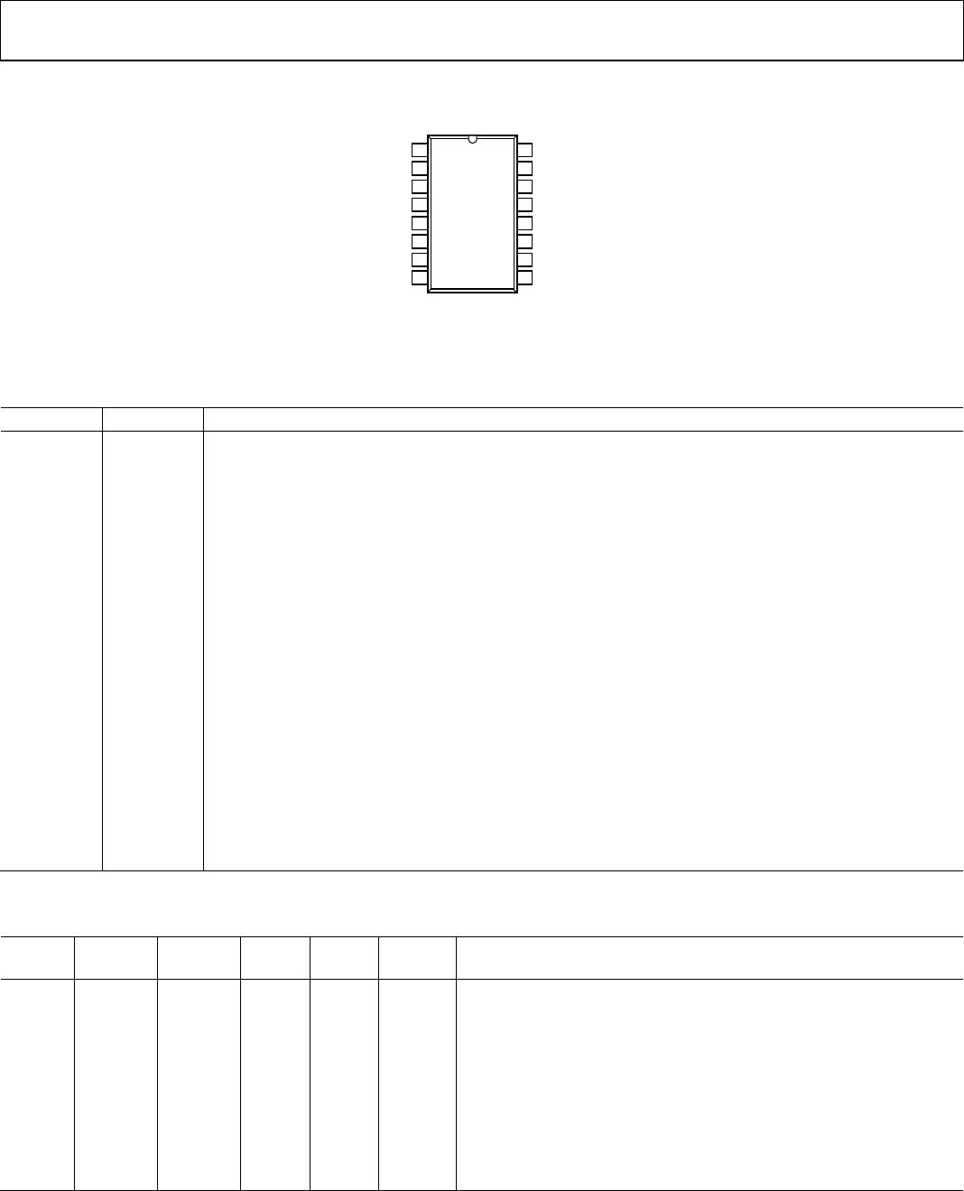
Figure 3. Pin Configuration
Table 12. Pin Function Descriptions
Pin No. Mnemonic Description
DD1
Primary Supply Voltage, 3.0 V to 5.5 V. Pin 1 and Pin 7 are internally connected to each other, and it is
recommended that both pins be externally connected to a common power source.
2, 8 GND
1
Ground Reference for the Primary Side of the Converter. Pin 2 and Pin 8 are internally connected to each
other, and it is recommended that both pins be connected to a common ground.
3, 11, 12, 14 NC No Internal Connection.
4 RC
IN
Regulation Control Input. In slave power configuration (RC
SEL
low), this pin is connected to the RC
OUT
pin of a
master isoPower device, or it is tied low to disable the converter. In master or standalone mode (RC
SEL
high),
this pin has no function. This pin is weakly pulled to the low state. In noisy environments, it should be tied low
or tied to a PWM control source. This pin must not be tied high if RC
SEL
is low; this combination causes excessive
voltage on the secondary side of the converter, damaging the ADuM6000 and possibly the devices that it powers.
5 RC
OUT
Regulation Control Output. In master power configuration (RC
SEL
high), this pin is connected to the RC
IN
pin of
a slave isoPower device to allow the ADuM6000 to regulate additional devices.
6 RC
SEL
Control Input. Sets either standalone/master mode (RC
SEL
high) or slave mode (RC
SEL
low). This pin is weakly
pulled to the high state. In noisy environments, tie this pin either high or low.
9, 15 GND
ISO
Ground Reference for the Secondary Side of the Converter. Pin 9 and Pin 15 are internally connected to each
other, and it is recommended that both pins be connected to a common ground.
10, 16 V
ISO
Secondary Supply Voltage Output for External Loads. 3.3 V (V
SEL
low) or 5.0 V (V
SEL
high). The 5.0 V output
functionality is not guaranteed for a 3.3 V primary supply input. Pin 10 and Pin 16 are internally connected
to each other, and it is recommended that both pins be externally connected.
13 V
SEL
Output Voltage Selection. When V
SEL
= V
ISO
, the V
ISO
setpoint is 5.0 V. When V
SEL
= GND
ISO
, the V
ISO
setpoint is 3.3 V.
This pin is weakly pulled to the high state. In noisy environments, tie this pin either high or low. In slave mode,
this pin has no function.
Table 13. Truth Table (Positive Logic)
RC
SEL
Input
RC
IN
Input
RC
OUT
Output
V
SEL
Input
V
DD1
Input
V
ISO
Output
Operation
H X PWM
1
H 5.0 V 5.0 V Master mode operation, self regulating.
H X PWM
1
L 5.0 V 3.3 V Master mode operation, self regulating.
H X PWM
1
H 3.3 V 5.0 V This configuration is not recommended due to poor efficiency.
H X PWM
1
L 3.3 V 3.3 V Master mode operation, self regulating.
OUT(EXT)
IN
2
Slave mode, RC
OUT(EXT)
supplied by a master
Power device.
L L L X X 0 V Low power mode, converter disabled.
L H H X X X This combination of RC
IN
and RC
SEL
is prohibited. Damage occurs on the
secondary side of the converter due to excess output voltage at V
ISO
.
RC
IN
must be low, or it must be connected to a PWM signal from a
master isoPower part.
1
PWM refers to the regulation control signal. This signal is derived from the secondary side regulator or from the RC
IN
input, depending on the value of RC
SEL
.
2
V
DD1
must be common between all isoPower devices being regulated by a master isoPower part.