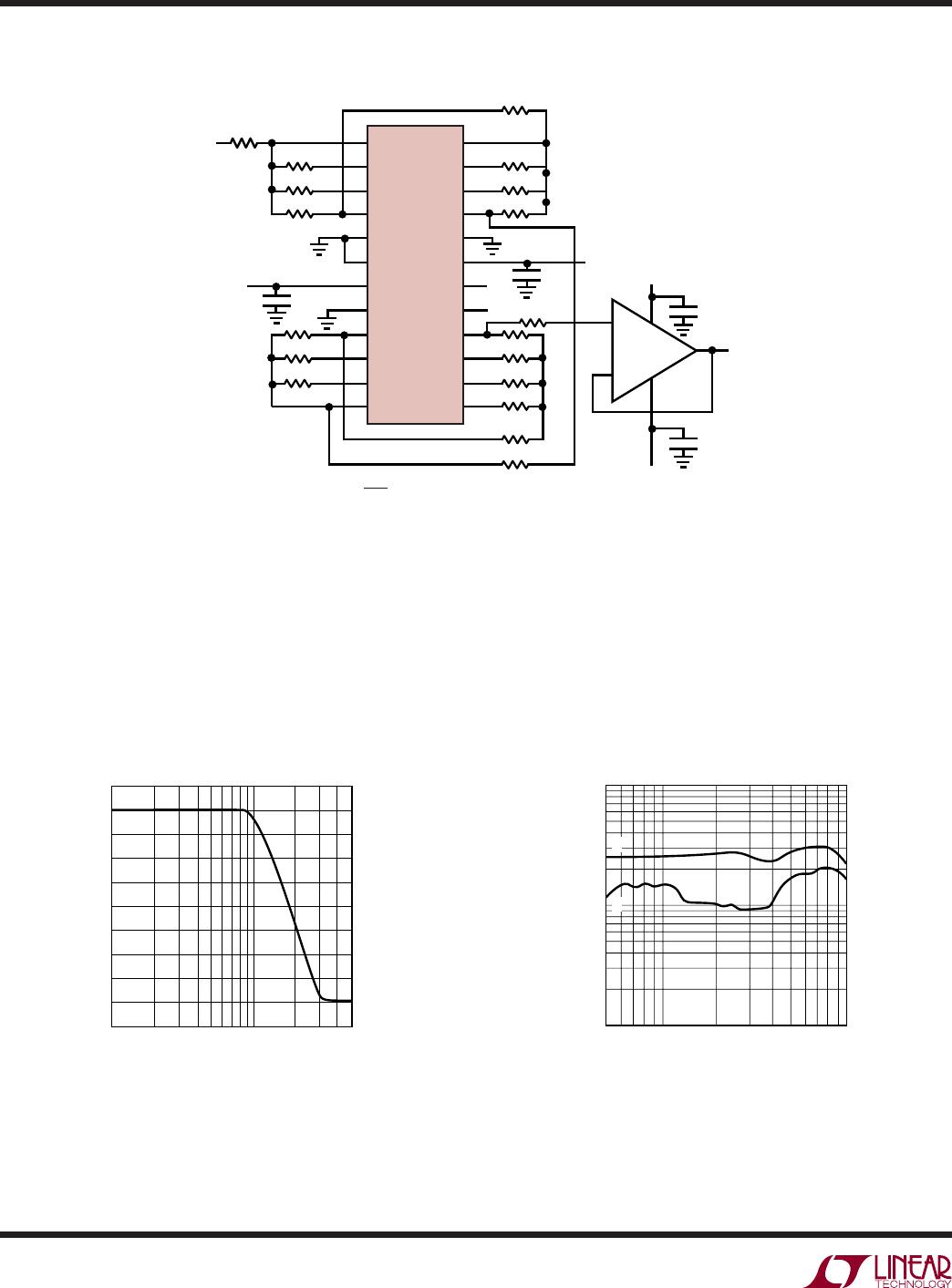
LTC1164
10
1164fa
Mode 3
Mode 3 is the second of the primary modes. In Mode 3, the
ratio of the external clock frequency to the center
frequency of each 2nd order section can be adjusted above
or below 50:1 or 100:1. Side D of the LTC1164 can only be
connected in Mode 3. Figure 7 illustrates Mode 3, the
classical state variable configuration, providing highpass,
bandpass, and lowpass 2nd order filter functions. Mode 3
is slower than Mode 1. Mode 3 can be used to make high
order all-pole bandpass, lowpass, highpass and notch
filters.
When the internal clock-to-center frequency ratio is set at
50:1, the design equations for Q and bandpass gain are
different from the 100:1 case.
This was done to provide
speed without penalizing the noise performance.
SECONDARY MODES
Mode 1b
Mode 1b is derived from Mode 1. In Mode 1b, Figure 8, two
additional resistors R5 and R6, are added to alternate the
amount of voltage feedback from the lowpass output into
the input of the SA (or SB or SC) switched capacitor
summer. This allows the filter clock-to-center frequency
ratio to be adjusted beyond 50:1 or 100:1. Mode 1b
maintains the speed advantages of Mode 1.
Mode 2
Mode 2 is a combination of Mode 1 and Mode 3, as shown
in Figure 9. With Mode 2, the clock-to-center frequency
ratio, f
CLK
/f
O
, is always less than 50:1 or 100:1. The
advantage of Mode 2 is that it provides less sensitivity to
resistor tolerances than does Mode 3. As in Mode 1,
Mode 2 has a notch output which depends on the clock
frequency, and the notch frequency is therefore less than
the center frequency, f
O
.
When the internal clock-to-center frequency ratio is set at
50:1, the design equations for Q and bandpass gain are
different from the 100:1 case.
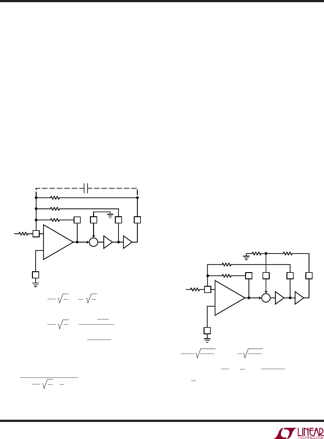
Figure 8. Mode 1b: 2nd Order Filter Providing Notch,
Bandpass, Lowpass
Figure 7. Mode 3: 2nd Order Filter Providing Highpass,
Bandpass, Lowpass
LTC1164 • MOO02
R3
R4
R2
HP S BP LP
R1
AGND
R2/R1;
1/4 LTC1164
f
o
=
; Q =
; H
OHP
= –
R3/R1;
H
OBP
= –
H
OBP
= –
MODE 3 (100:1):
R4/R1
H
OLP
= –
R4/R1
; H
OLP
= –
R2/R1;
H
OLP
= –
f
CLK
100
+
+
Σ
V
IN
C
C
R3
R2
R2
R4
f
o
=
; Q =
MODE 3 (50:1):
; THEN CALCULATE R1 TO SET
THE DESIRED GAIN
R3 =
R2
NOTE: THE 50:1 EQUATIONS FOR MODE 3 ARE DIFFERENT FROM THE EQUATIONS
FOR MODE 3 OPERATION OF THE LTC1059, LTC1060 AND LTC1061. START WITH
f
o
, CALCULATE R2/R4, SET R4; FROM THE Q VALUE, CALCULATE R3:
f
CLK
50
R2
R4
R2
R4
R3/R1
1 – (R3/16R4)
1.005 (R2/R4)
(R2/R3) – (R2/16R4);
+
1.005
Q
R2
R4
R2
16R4
LTC1164 • MOO03
R3
R6 R5
R2
NS BPLP
R1
AGND
f
o
=
; Q =
= –
;
; (R5//R6) < 5k
H
ON1
(f 0) = H
ON2
f
H
OBP
= –
; H
OLP
=;
f
CLK
100(50)
+
+
Σ
V
IN
f
CLK
2
R3
R2
R3
R1
R2
R1
; f
n
= f
o
R6
R5 + R6
– R2/R1
R6/(R5 + R6)
R6
R5 + R6
()
ODES OF OPERATIO
U
W
LTC1164
11
1164fa
Mode 3A
This is an extension of Mode 3 where the highpass and
lowpass output are summed through two external resis-
tors R
H
and R
L
to create a notch. This is shown in Figure
10. Mode 3A is more versatile than Mode 2 because the
notch frequency can be higher or lower than the center
frequency of the 2nd order section. The external op amp of
Figure 10 is not always required. When cascading the
sections of the LTC1164, the highpass and lowpass
outputs can be summed directly into the inverting input of
the next section. The topology of Mode 3A is useful for
elliptic highpass and notch filters with clock to cutoff
frequency ratios higher than 100:1. This is often required
to extend the allowed input signal frequency range and to
avoid premature aliasing.
When the internal clock-to-center frequency ratio is set at
50:1, the design equations for Q and bandpass gain are
different from the 100:1 case.
Figure 9. Mode 2: 2nd Order Filter Providing Notch, Bandpass, Lowpass
ODES OF OPERATIO
U
W
LTC1164 • MOO04
R3
R4
R2
NS BPLP
R1
1/4 LTC1164
f
o
=
1 +
1 +
R3/R1;
; H
OLP
=
H
OBP
= –
H
OBP
= –
MODE 2 (100:1):
f
CLK
100
+
+
Σ
V
IN
R3
R2
R2
R4
; f
n
=
; Q =
; THEN CALCULATE R1 TO SET THE DESIRED GAIN
R3 =
R2
NOTE: THE 50:1 EQUATIONS FOR MODE 2 ARE DIFFERENT FROM THE EQUATIONS
FOR MODE 2 OPERATION OF THE LTC1059, LTC1060 AND LTC1061. START WITH
f
o
, CALCULATE R2/R4, SET R4; FROM THE Q VALUE, CALCULATE R3:
f
CLK
50
; f
n
=
; Q =
f
CLK
50
R3/R1
1 – (R3/16R4)
+
1.005
Q
R2
R4
R2
16R4
f
o
=
1 +
MODE 2 (50:1):
f
CLK
50
R2
R4
1 +
R2
R4
; H
ON1
(f 0) =
–R2/R1
1 + (R2/R4)
; H
OLP
=
–R2/R1
1 + (R2/R4)
–R2/R1
1 + (R2/R4)
H
ON1
(f 0) =
R2/R1
1 + (R2/R4)
1.005 (1 + R2/R4)
(R2/R3) – (R2/16R4)
= – R2/R1
H
ON2
f
f
CLK
2
()
= – R2/R1
; H
ON2
f
f
CLK
2
()
Figure 10. Mode 3A: 2nd Order Filter Providing Highpass, Bandpass, Lowpass, Notch
LTC1164 • MOO05
H
OBP
= –
H
OLP
NOTE: THE 50:1 EQUATIONS FOR MODE 3A ARE DIFFERENT FROM THE EQUATIONS
FOR MODE 3A OPERATION OF THE LTC1059, LTC1060 AND LTC1061. START WITH
f
o
, CALCULATE R2/R4, SET R4; FROM THE Q VALUE, CALCULATE R3:
; f
n
=
f
CLK
50
R3/R1
1 – (R3/16R4)
f
o
=
MODE 3A (50:1):
MODE 3A (100:1):
f
CLK
50
R2
R4
R4
R1
R
H
R
L
R
G
R
L
R
G
R
H
R
G
R
L
H
OHP
; THEN CALCULATE R1 TO SET
THE DESIRED GAIN
R3 =
R2
+
1.005
Q
R2
R4
R2
16R4
; H
OLP
(f = 0) = – R4/R1
R4/R1;
H
OLP
= –
H
ON
(f = f
o
) = Q
H
ON1
(f 0) =
=
; H
ON2
f
f
CLK
2
()
= –R2/R1
; H
OHP
f
; f
n
=
f
CLK
100
f
o
=
f
CLK
100
R2
R4
R2
R4
R3
R2
R
H
R
L
; H
OHP
= – R2/R1; H
OBP
= –R3/R1
f
CLK
2
(
)
(
)
R3
R4
R2
HP S BP LP
NOTCH
EXTERNAL OP AMP OR
INPUT OP AMP OF THE
LTC1164, SIDE A, B, C, D
R1
AGND
1/4 LTC1164
+
+
Σ
V
IN
R
H
R
L
R
G
C
C
+
; Q =
; Q =
1.005 (R2/R4)
(R2/R3) – (R2/16R4)
×
R2
R1
R
G
R
H
×
LTC1164
12
1164fa
Figure 11. 8th Order Lowpass Butterworth, Passband Noise 90µV
RMS
(Also Refer to the LTC1164-5)
LTC1164 8th Order Butterworth,
f
CLK
= 500kHz, f
3dB
= 10kHz
LTC1164 8th Order Butterworth,
f
CLK
= 500kHz, f
3dB
= 10kHz ±8V,
A. 2V
RMS
, B. 4V
RMS
LTC1164 • AC02
FREQUENCY (Hz)
1k
90.00
GAIN (dB)
70.00
40.00
10.00
10k 50k
10.00
80.00
60.00
50.00
30.00
0.0
20.00
FREQUENCY (Hz)
500
0.001
HARMONIC DISTRIBUTION (%)
0.010
0.1
1k 10k
LTC1164 • AC03
A
B
LTC1164 • AC01
124
2
23
3
22
421
5
20
6
19
18
7
8
17
916
10 15
11
14
12
13
8V
82.5k
88.7k
88.7k
76.8k
76.8k
90.9k
90.9k
15V
-15V
-8V
8V
75k
130k
154k
154k
130k
76.8k
75k
154k
196k
V
IN
V
OUT
f
CLK
0.1µF
0.1µF
0.1µF
0.1µF
f
CLK
= 500kHz
f
–3dB
=
f
CLK
50
LT1056
1k
+
LTC1164
TYPICAL APPLICATIO S
U

LTC1164ACN#PBF

Mfr. #:
Manufacturer:
Analog Devices Inc.
Description:
Active Filter Quad 20kHz LP Sw Cap Filter
Lifecycle:
New from this manufacturer.
Delivery:
DHL FedEx Ups TNT EMS
Payment:
T/T Paypal Visa MoneyGram Western Union