8
FN6320.3
April 18, 2007
Electrical Specifications ISL884xAM - Recommended operating conditions unless otherwise noted. Refer to Block Diagram and
Typical Application schematic. V
DD
= 15V, RT = 10kΩ, CT = 3.3nF, T
A
= -55 to +125°C (Note 7), Typical values
are at T
A
= +25°C
PARAMETER TEST CONDITIONS MIN TYP MAX UNITS
UNDERVOLTAGE LOCKOUT
START Threshold (ISL8840A, ISL8841A) 6.5 7.0 7.5 V
START Threshold (ISL8843A, ISL8845A) 8.0 8.4 9.0 V
START Threshold (ISL8842A, ISL8844A) (Note 10) 13.3 14.3 15.3 V
STOP Threshold (ISL8840A, ISL8841A) 6.1 6.6 6.9 V
STOP Threshold (ISL8843A, ISL8845A) 7.3 7.6 8.0 V
STOP Threshold (ISL8842A, ISL8844A) 8.0 8.8 9.6 V
Hysteresis (ISL8840A, ISL8841A) - 0.4 - V
Hysteresis (ISL8843A, ISL8845A) - 0.8 - V
Hysteresis (ISL8842A, ISL8844A) - 5.4 - V
Startup Current, I
DD
V
DD
< START Threshold - 90 125 μA
Operating Current, I
DD
(Note 8) - 2.9 4.0 mA
Operating Supply Current, I
D
Includes 1nF GATE loading - 4.75 5.5 mA
REFERENCE VOLTAGE
Overall Accuracy Over line (V
DD
= 12V to 30V), load,
temperature
4.900 5.000 5.050 V
Long Term Stability T
A
= +125°C, 1000 hours (Note 9) - 5 - mV
Current Limit, Sourcing -20 - - mA
Current Limit, Sinking 5--mA
CURRENT SENSE
Input Bias Current V
CS
= 1V -1.0 - 1.0 μA
CS Offset Voltage V
CS
= 0V (Note 9) 95 100 105 mV
COMP to PWM Comparator Offset Voltage V
CS
= 0V (Note 9) 0.80 1.15 1.30 V
Input Signal, Maximum 0.97 1.00 1.03 V
Gain, A
CS
= ΔV
COMP
/ΔV
CS
0 < V
CS
< 910mV, V
FB
= 0V 2.5 3.0 3.5 V/V
CS to OUT Delay -3560ns
ERROR AMPLIFIER
Open Loop Voltage Gain (Note 9) 60 90 - dB
Unity Gain Bandwidth (Note 9) 1.0 1.5 - MHz
Reference Voltage V
FB
= V
COMP
2.460 2.500 2.535 V
FB Input Bias Current V
FB
= 0V -1.0 -0.2 1.0 μA
COMP Sink Current V
COMP
= 1.5V, V
FB
= 2.7V 1.0 - - mA
COMP Source Current V
COMP
= 1.5V, V
FB
= 2.3V -0.4 - - mA
COMP VOH V
FB
= 2.3V 4.80 - VREF V
COMP VOL V
FB
= 2.7V 0.4 - 1.0 V
PSRR Frequency = 120Hz, V
DD
= 12V to
30V (Note 9)
60 80 - dB
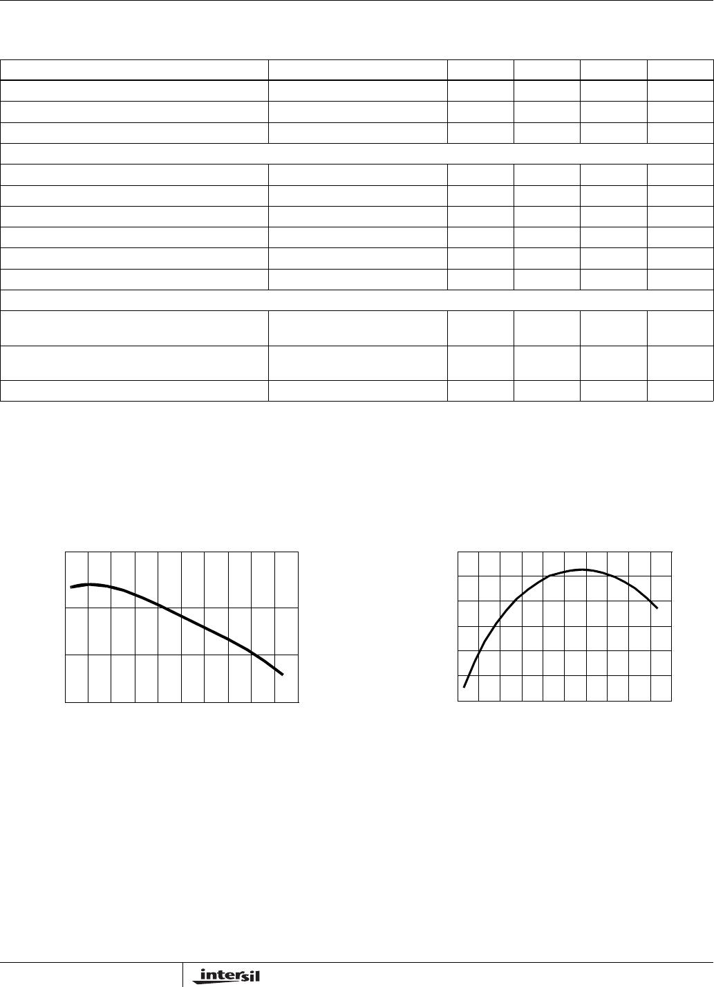
OSCILLATOR
Frequency Accuracy Initial, T
A
= +25°C 485153kHz
Frequency Variation with V
DD
T
A
= +25°C, (f
30V
- f
10V
)/f
30V
-0.21.0%
Temperature Stability (Note 9) - - 5 %
ISL8840A, ISL8841A, ISL8842A, ISL8843A, ISL8844A, ISL8845A