NB3U23C
http://onsemi.com
3
Table 3. MAXIMUM RATINGS (Note 2)
Symbol
Parameter Condition 1 Condition 2 Rating Unit
V
DD
Supply Voltage 3.6 V
V
in
Input Voltage –0.5 ≤ V
I
≤ 2.5 V
I
D
Output Current 25 mA
T
A
Operating Temperature Range, Industrial −40 to +85 °C
T
stg
Storage Temperature Range −65 to +150 °C
q
JA
Thermal Resistance (Junction−to−Ambient) 0 lfpm
500 lfpm (Note 3)
0 lfpm
500 lfpm (Note 3)
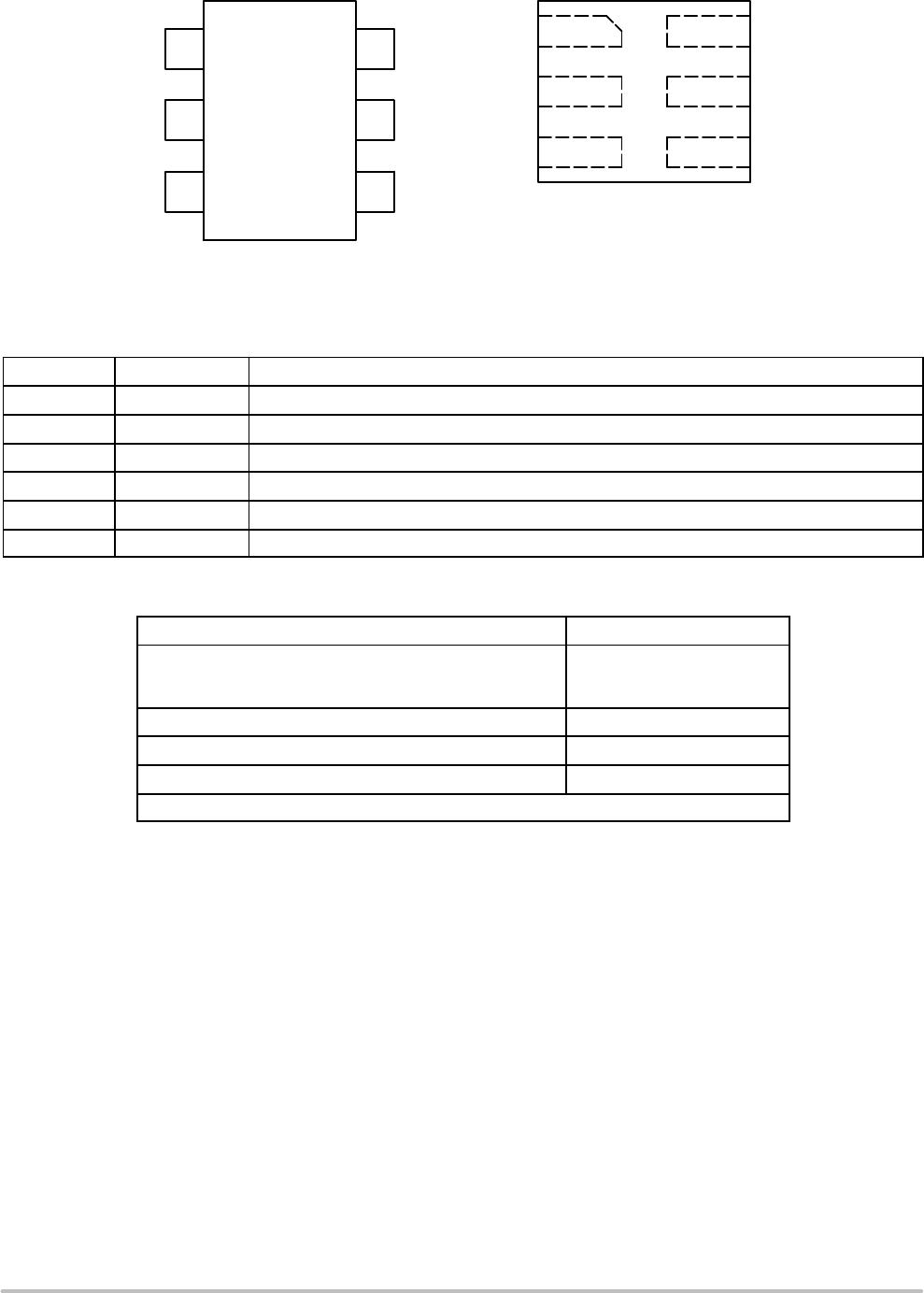
SC70−6
UDFN−6
210
126
245
172
°C/W
q
JC
Thermal Resistance (Junction−to−Case) (Note 3) SC70−6
UDFN−6
100
150
°C/W
T
sol
Wave Solder 260 °C
Stresses exceeding those listed in the Maximum Ratings table may damage the device. If any of these limits are exceeded, device functionality
should not be assumed, damage may occur and reliability may be affected.
2. Maximum ratings applied to the device are individual stress limit values (not normal operating conditions) and not valid simultaneously. If
stress limits are exceeded device functional operation is not implied, damage may occur and reliability may be affected.
3. JEDEC standard multilayer board − 2S2P (2 signal, 2 power).
Table 4. ELECTRICAL CHARACTERISTICS (VDD = 1.2 ±5% V, GND = 0 V, T
A
= −40°C to +85°C)
Symbol
Characteristic Conditions Min Typ Max Unit
DIDD
Power Supply Current
(Single Channel Switching @ 52 MHz)
C
L
= 20 pF
C
L
= 5 pF
C
L
= 1 pF
2.5
1.5
1
mA
Power Supply Current
(Both Channels Switching @ 52 MHz)
C
L
= 20 pF
C
L
= 5 pF
C
L
= 1 pF
5
3
2
mA
I
off
Standby Current Vi = V
IH
Max or GND;
V
DD
= 1.2 V, No Output Load
10
mA
V
IH
Input High Voltage 0.65 * VDD 1.98 V
V
IL
Input Low Voltage 0 0.35 * VDD V
V
OH
Output High Voltage C
L
= 20 pF
R
L
= 100 kW
0.75 * VDD VDD V
V
OL
Output Low Voltage C
L
= 20 pF
R
L
= 100 kW
0 0.25 * VDD V
C
in
Input Capacitance 5 pF
F
clk
Operating Frequency Range 0 52 MHz
t
PD
Propagation Delay INx to OUTx
C
L
= 20 pF, R
L
= 100 kW
5 ns
Phase Noise Floor Density
(Notes 4 and 5)
C
L
= 20 pF
R
L
= 100 kW
−150 dBc/Hz
Additive RMS Phase Jitter
(Notes 5 and 6)
C
L
= 20 pF
R
L
= 100 kW
Offset Frequency Range:
50 kHz to 10 MHz
0.15 0.25 ps
DC Output Duty Cycle (Note 7) Input Duty Cycle = 50%,
Min Input Slew Rate = 1 V/ns
45 55 %
tr/tf Output Rise/Fall Times 0.2 * V
DD
to 0.8 * VDD
C
L
= 20 pF
R
L
= 100 kW
2 ns
Product parametric performance is indicated in the Electrical Characteristics for the listed test conditions, unless otherwise noted. Product
performance may not be indicated by the Electrical Characteristics if operated under different conditions.
4. White noise floor.
5. This parameter refers to the random jitter only.
6. The output RMS phase jitter can be calculated using the following equation:
(Output RMS Phase Jitter)
2
= (Input RMS Phase Jitter)
2
+ (Additive RMS Phase Jitter)
2
7. Measured with input voltage swing from 0 V to 1.8 V.