AD8314
Rev. B | Page 18 of 20
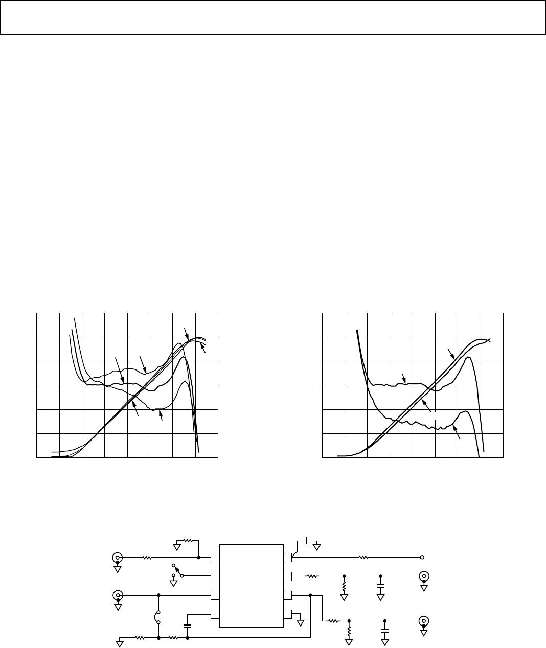
OPERATION AT 2.7 GHz
While the AD8314 is specified to operate at frequencies up to
2.5 GHz, it works at higher frequencies, although it does exhibit
slightly higher output voltage temperature drift.
Figure 43
shows the transfer function of a typical device at 2.7 GHz, at
ambient as well as hot and cold temperatures.
Figure 44 shows the transfer function of the AD8314 when
driven by both an unmodulated sine wave and a 64 QAM
signal. As previously discussed, the higher peak-to-average ratio
of the 64 QAM signal causes an increase in the intercept.
In this case, the intercept increases by approximately 1.5 dB,
causing the overall transfer function to drop by the same
amount. For precision operation, the AD8314 should be
calibrated for each signal type that is driving it.
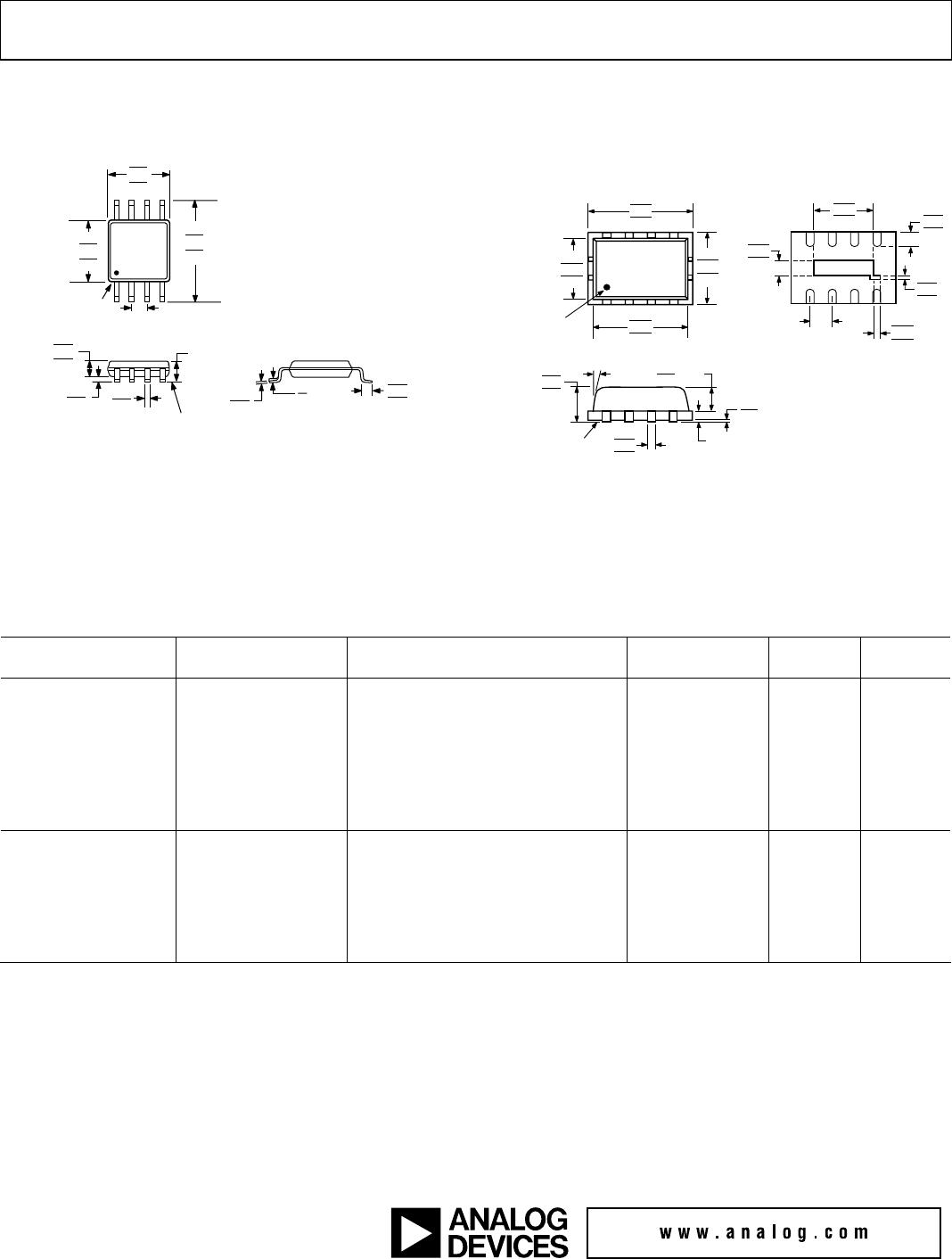
USING THE LFCSP PACKAGE
On the underside of the LFCSP package, there is an exposed,
compressed paddle. This paddle is internally connected to the
chips ground. While the paddle can be connected to the printed
circuit boards ground plane, there is no thermal or electrical
requirement to do this.
EVALUATION BOARD
Figure 45 shows the schematic of the AD8314 MSOP
evaluation board. The layout and silkscreen of the component
side are shown in
Figure 46 and Figure 47. An evaluation board
is also available for the LFCSP package. (For exact part numbers,
see the
Ordering Guide.) Apart from the slightly smaller device
footprint, the LFCSP evaluation board is identical to the MSOP
board. The board is powered by a single supply in the 2.7 V to
5.5 V range. The power supply is decoupled by a single 0.1 µF
capacitor. Additional decoupling, in the form of a series resistor
or inductor in R9, can also be added.
Table 7 details the various
configuration options of the evaluation board.
1.2
0
–70 10
INPUT POWER (dBm)
V
UP
(V)
ERROR (dB)
3
–3
–2
–1
0
1
21.0
0.8
0.6
0.4
0.2
+25°C
–40°C
–40°C
+25°C
+80°C
+80°C
–60 –50 –40 –30 –20 –10 0
01086-043
Figure 43. Operating at 2.7 GHz
1.2
0
–70 10
INPUT POWER (dBm)
V
UP
(V)
ERROR (dB)
3
–3
–2
–1
0
1
21.0
0.8
0.6
0.4
0.2
–60 –50 –40 –30 –20 –10 0
CW
CW
64 QAM
64 QAM
01086-044
Figure 44. Shift in Transfer Function due to 64 QAM
V
POS
VSET
LK1
INPUT
SW1
V_DN
V_UP
VPOS
C1
0.1µF
1
2
3
4
ENBL
RFIN
AD8314
8
7
6
5
VSET
FLTR
V_DN
VPOS
COMM
V_UP
R2
52.3
R1
0
R7
0
R8
OPEN
C4
(OPEN)
R4
(OPEN)
C2
(OPEN)
R6
(OPEN)
C3
(OPEN)
R3
0
R5
0
R9
0
01086-045
Figure 45. Evaluation Board Schematic
AD8314
Rev. B | Page 19 of 20
01086-046
Figure 46. Layout of Component Side (MSOP)
01086-047
Figure 47. Silkscreen of Component Side (MSOP)
Table 7. Evaluation Board Configuration Options
Component Function Default Condition
TP1, TP2 Supply and Ground Vector Pins. Not Applicable
SW1
Device Enable: When in Position A, the ENBL pin is connected to +V
S
and the AD8314 is in
operating mode. In Position B, the ENBL pin is grounded, putting the device in power-down mode.
SW1 = A
R1, R2
Input Interface. The 52.3 Ω resistor in Position R2 combines with the AD8314’s internal input
impedance to give a broadband input impedance of around 50 Ω. A reactive match can be
implemented by replacing R2 with an inductor and R1 (0 Ω) with a capacitor. Note that the
AD8314’s RF input is internally ac-coupled.
R2 = 52.3 Ω (Size 0603)
R1 = 0 Ω (Size 0402)
R3, R4, C2,
R5, R6, C3
Output Interface. R4, C2, R6, and C3 can be used to check the response of V_UP and V_DN to
capacitive and resistive loading. R3/R4 and R5/R6 can be used to reduce the slope of V_UP
and V_DN.
R4 = C2 = R6 =
C3 = Open (Size 0603)
R3= R5 = 0 Ω (Size 0603)
C1, R9
Power Supply Decoupling. The nominal supply decoupling consists of a 0.1 μF capacitor (C1).
A series inductor or small resistor can be placed in R9 for additional decoupling.
C1 = 0.1 μF (Size 0603)
R9 = 0 Ω (Size 0603)
C4
Filter Capacitor. The response time of V_UP and V_DN can be modified by placing a capacitor
between FILTR and V_UP.
C4 = Open (Size 0603)
R7, R8
Slope Adjust. By installing resistors in R7 and R8, the nominal slope of 20 mV/dB can be
increased. See
Increasing the Logarithmic Slope in Measurement Mode for more details.
R7 = 0 Ω (Size 0603)
R8 = Open (Size 0603)
LK1
Measurement/Controller Mode. LK1 shorts V_UP to VSET, placing the AD8314 in measurement
mode. Removing LK1 places the AD8314 in controller mode.
LK1 = Installed
AD8314
Rev. B | Page 20 of 20
OUTLINE DIMENSIONS
COMPLIANT TO JEDEC STANDARDS MO-187-AA
0.80
0.60
0.40
4
8
1
5
PIN 1
0.65 BSC
SEATING
PLANE
0.38
0.22
1.10 MAX
3.20
3.00
2.80
COPLANARITY
0.10
0.23
0.08
3.20
3.00
2.80
5.15
4.90
4.65
0.15
0.00
0.95
0.85
0.75
Figure 48. 8-Lead Mini Small Outline Package [MSOP]
(RM-8)
Dimensions shown in millimeters
0.30
0.23
0.18
SEATING
PLANE
0.20 REF
0.80 MAX
0.65 TYP
1.00
0.85
0.80
1.89
1.74
1.59
0.50 BSC
0.60
0.45
0.30
0.55
0.40
0.30
0.15
0.10
0.05
0.25
0.20
0.15
BOTTOM VIEW
*
4 1
58
3.25
3.00
2.75
1.95
1.75
1.55
2.95
2.75
2.55
PIN 1
INDICATO
R
2.25
2.00
1.75
TOP VIEW
0.05 MAX
0.02 NOM
12° MAX
EXPOSED PAD
Figure 49. 8-Lead Lead Frame Chip Scale Package [LFCSP_VD]
2 mm × 3 mm Body, Very Thin, Dual Lead (CP-8-1)
Dimensions shown in millimeters
ORDERING GUIDE
Model Temperature Range Package Description Package Option Branding
Ordering
Quantity
AD8314ARM −40°C to +85°C 8-Lead MSOP, Tube RM-8 J5A 50
AD8314ARM-REEL −40°C to +85°C 8-Lead MSOP, 13" Tape and Reel RM-8 J5A 3,000
AD8314ARM-REEL7 −40°C to +85°C 8-Lead MSOP, 7" Tape and Reel RM-8 J5A 1,000
AD8314ARMZ
1
−40°C to +85°C 8-Lead MSOP, Tube RM-8 J5A# 50
AD8314ARMZ-REEL
1
−40°C to +85°C 8-Lead MSOP, 13" Tape and Reel RM-8 J5A# 3,000
AD8314ARMZ-REEL7
1
−40°C to +85°C 8-Lead MSOP, 7" Tape and Reel RM-8 J5A# 1,000
AD8314-EVAL MSOP Evaluation Board
AD8314ACP-REEL −40°C to +85°C 8-Lead LFCSP_VD, 13" Tape and Reel CP-8-1 J5 10,000
AD8314ACP-REEL7 −40°C to +85°C 8-Lead LFCSP_VD, 7" Tape and Reel CP-8-1 J5 3,000
AD8314ACP-WP −40°C to +85°C 8-Lead LFCSP_VD, Waffle Pack CP-8-1 J5 50
AD8314ACPZ-REEL
1
−40°C to +85°C 8-Lead LFCSP_VD, 13" Tape and Reel CP-8-1 0F 10,000
AD8314ACPZ-RL7
1
−40°C to +85°C 8-Lead LFCSP_VD, 7" Tape and Reel CP-8-1 0F 3,000
AD8314ACP-EVAL LFCSP_VD Evaluation Board
T
1
Z = Pb-free part, # denotes lead-free product may be top or bottom marked.
©2006 Analog Devices, Inc. All rights reserved. Trademarks and
registered trademarks are the property of their respective owners.
C01086-0-5/06(B)
TTT

AD8314ARM-REEL7

Mfr. #:
Manufacturer:
Analog Devices Inc.
Description:
RF Detector RF Detector/Cntlr 100MHz-2.7GHz 45dB
Lifecycle:
New from this manufacturer.
Delivery:
DHL FedEx Ups TNT EMS
Payment:
T/T Paypal Visa MoneyGram Western Union