1:2, DIFFERENTIAL-TO-LVCMOS/LVTTL ZERO DELAY CLOCK
GENERATOR
5 Rev C 7/13/15
87002-02 DATA SHEET
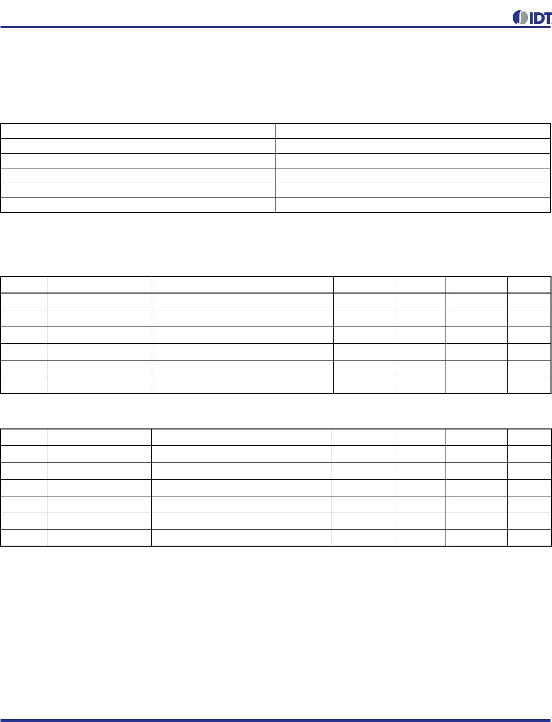
Absolute Maximum Ratings
NOTE: Stresses beyond those listed under Absolute Maximum Ratings may cause permanent damage to the device.
These ratings are stress specifications only. Functional operation of product at these conditions or any conditions beyond
those listed in the DC Characteristics or AC Characteristics is not implied. Exposure to absolute maximum rating conditions for
extended periods may affect product reliability.
DC Electrical Characteristics
Table 4A. Power Supply DC Characteristics, V
DD
= V
DDA
= V
DDO
= 3.3V ± 5%, T
A
= 0°C to 70°C
Table 4B. Power Supply DC Characteristics, V
DD
= V
DDA
= V
DDO
= 2.5V ± 5%, T
A
= 0°C to 70°C
Item Rating
Supply Voltage, V
DD
4.6V
Inputs, V
I
-0.5V to V
DD
+ 0.5V
Outputs, V
O
-0.5V to V
DDO
+ 0.5V
Package Thermal Impedance,
JA
73.2C/W (0 lfpm)
Storage Temperature, T
STG
-65C to 150C
Symbol Parameter Test Conditions Minimum Typical Maximum Units
V
DD
Core Supply Voltage 3.135 3.3 3.465 V
V
DDA
Analog Supply Voltage 3.135 3.3 3.465 V
V
DDO
Output Supply Voltage 3.135 3.3 3.465 V
I
DD
Power Supply Current 100 mA
I
DDA
Analog Supply Current 16 mA
I
DDO
Output Supply Current 6mA
Symbol Parameter Test Conditions Minimum Typical Maximum Units
V
DD
Core Supply Voltage 2.375 2.5 2.625 V
V
DDA
Analog Supply Voltage 2.375 2.5 2.625 V
V
DDO
Output Supply Voltage 2.375 2.5 2.625 V
I
DD
Power Supply Current 96 mA
I
DDA
Analog Supply Current 15 mA
I
DDO
Output Supply Current 6mA

