LT1996
11
1996f
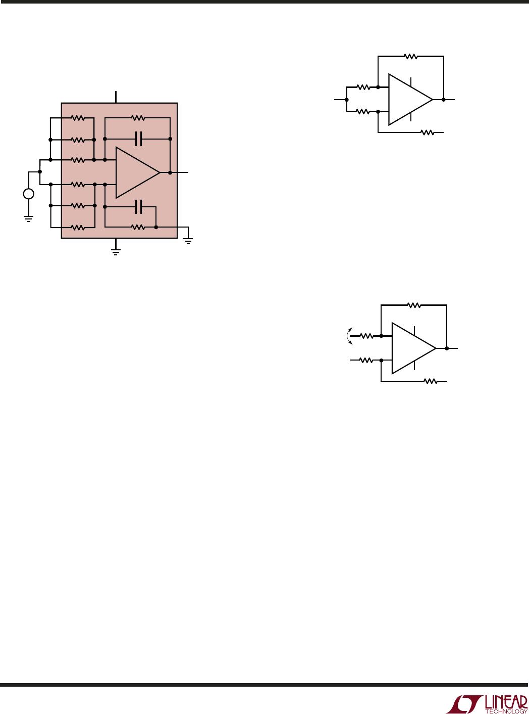
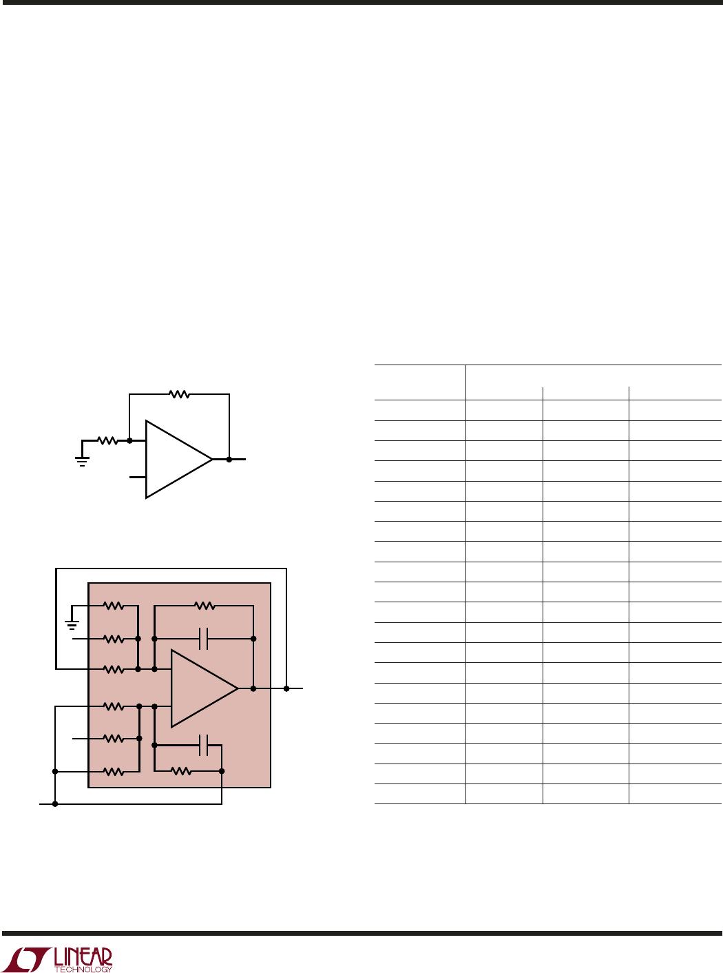
representation of the circuit on the top. The LT1996 is
shown on the bottom configured in a precision gain of 9.1.
One of the benefits of the noninverting op amp configura-
tion is that the input impedance is extremely high. The
LT1996 maintains this benefit. Given the finite number of
available feedback resistors in the LT1996, the number of
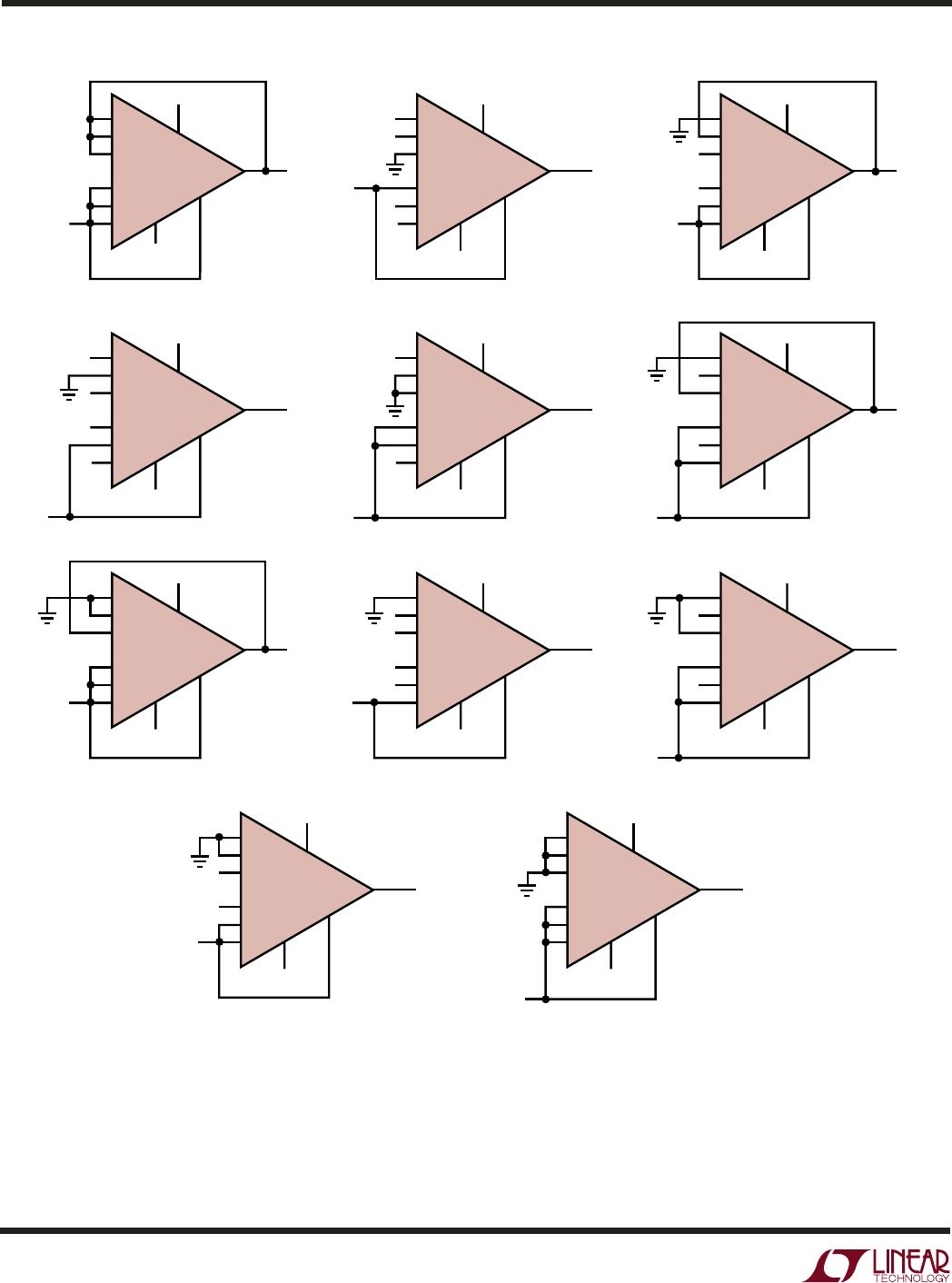
gain configurations is also finite. The complete list of such
Hi-Z input noninverting gain configurations is shown in
Table 1. Many of these are also represented in Figure 5 in
schematic form. Note that the P-side resistor inputs have
been connected so as to match the source impedance
seen by the internal op amp inputs. Note also that gain and
noise gain are identical, for optimal precision.
Table 1. Configuring the M Pins for Simple Noninverting Gains.
The P Inputs are driven as shown in the examples on the next
page
M81, M27, M9 Connection
Gain M81 M27 M9
1 Output Output Output
1.08 Output Output Grounded
1.11 Output Float Grounded
1.30 Output Grounded Output
1.32 Float Output Grounded
1.33 Output Grounded Float
1.44 Output Grounded Grounded
3.19 Grounded Output Output
3.7 Float Grounded Output
3.89 Grounded Output Float
4.21 Grounded Output Grounded
9.1 Grounded Float Output
10 Float Float Grounded
11.8 Grounded Grounded Output
28 Float Grounded Float
37 Float Grounded Grounded
82 Grounded Float Float
91 Grounded Float Grounded
109 Grounded Grounded Float
118 Grounded Grounded Grounded
suggested in Figure 1: raise V
REF
, lower V
EE
, or provide
some negative V
MORE
.
Likewise, from the lower common mode extreme, making
the negative input more negative will raise the output
voltage, limited by V
CC
– 0.04V.
MIN V
MORE
= (V
REF
– V
CC
+ 0.04V) • R
G
/R
F
(should be negative)
Again, the additional input range calculated here is only
available provided the other remaining constraint is not
violated, the maximum voltage allowed on the pin.
The Classical Noninverting Amplifier: High Input Z
Perhaps the most common op amp configuration is the
noninverting amplifier. Figure 4 shows the textbook
Figure 4. The LT1996 as a Classical Noninverting Op Amp
APPLICATIO S I FOR ATIO
WUU
U
4pF
4pF
–
+
R
F
R
G
V
IN
V
IN
V
OUT
V
OUT
V
OUT
= GAIN • V
IN
GAIN = 1 + R
F
/R
G
–
+
1996 F04
450k/81
450k/27
450k/9
450k/81
450k/27
450k/9
450k
450k
8
6
5
9
10
1
2
3
LT1996
CLASSICAL NONINVERTING OP AMP CONFIGURATION.
YOU PROVIDE THE RESISTORS.
CLASSICAL NONINVERTING OP AMP CONFIGURATION
IMPLEMENTED WITH LT1991. R
F
= 45k, R
G
= 5.6k, GAIN = 9.1.
GAIN IS ACHIEVED BY GROUNDING, FLOATING OR FEEDING BACK
THE AVAILABLE RESISTORS TO ARRIVE AT DESIRED R
F
AND R
G
.
WE PROVIDE YOU WITH <0.1% RESISTORS.
4pF
4pF