LT1996
18
1996f
Difference Amplifier: Additional Integer Gains Using
Cross-Coupling
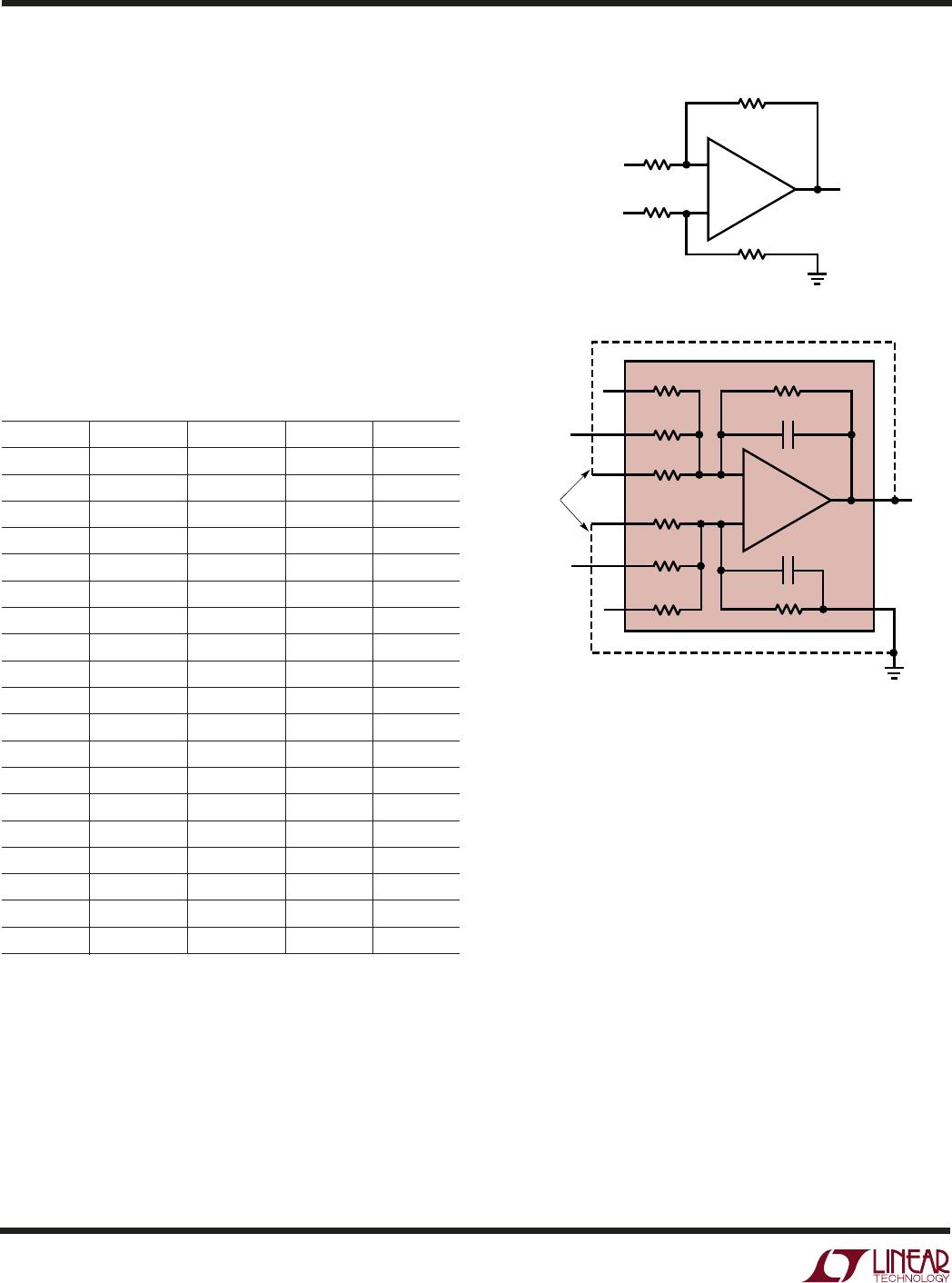
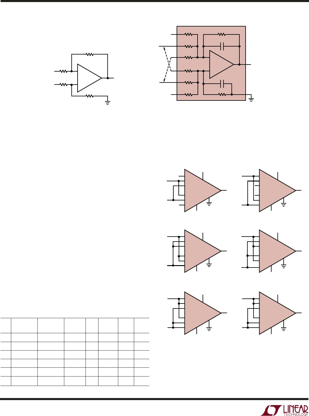
Figure 12 shows the basic difference amplifier as well as
the LT1996 in a difference gain of 27. But notice the effect
of the additional dashed connections. This is referred to as
“cross-coupling” and has the effect of reducing the differ-
ential gain from 27 to 18. Using this method, additional
integer gains are achievable, as shown in Table 5 below.
Note that the equations can be written by inspection from
the V
IN
+
connections, and that the V
IN
–
connections are
simply the opposite (swap P for M and M for P). The
method is the same as for the LT1991, except that the
LT1996 applies a multiplier of 9. Noise gain, bandwidth,
and input impedance specifications for the various cases
are also tabulated, as these are not obvious. Schematics
are provided in Figure 13.
Table 5. Connections Using Cross-Coupling. Note That Equations
Can Be Written by Inspection of the V
IN
+
Column
Gain Noise –3dB BW R
IN
+
R
IN
–
Gain V
IN
+
V
IN
–
Equation Gain kHz Typ kΩ Typ kΩ
18 P27, M9 M27, P9 27 – 9 39 14 46 16
45 P81, M27, M9 M81, P27, P9 81 – 27 – 9 117 5 12 6
54 P81, M27 M81, P27 81 – 27 108 5 16 6
63 P81, P9, M27 M81, M9, P27 81 + 9 – 27 117 5 16 5
72 P81, M9 M81, P9 81 – 9 90 6 45 6
99 P81, P27, M9 M81, M27, P9 81 + 27 – 9 117 5 45 4
Figure 12. Another Method of Selecting Difference Gain Is “Cross-Coupling.”
The Additional Method Means the LT1996 Provides Extra Integer Gains
Figure 13. Integer Gain Difference
Amplifiers Using Cross-Coupling
APPLICATIO S I FOR ATIO
WUU
U
1996 F13
V
S
–
V
S
+
V
S
–
V
S
+
V
S
–
V
S
+
V
S
–
V
S
+
M81
M27
M9
P9
P27
P81
OUT
V
CC
V
OUT
V
EE
REF
LT1996
8
9
10
1
2
3
7
6
5
4
M81
M27
M9
P9
P27
P81
OUT
V
CC
V
OUT
V
EE
REF
LT1996
8
9
10
1
2
3
7
6
5
4
M81
M27
M9
P9
P27
P81
OUT
V
CC
V
OUT
V
EE
REF
LT1996
8
9
10
1
2
3
7
6
5
4
M81
M27
M9
P9
P27
P81
OUT
V
CC
V
OUT
V
EE
REF
LT1996
8
9
10
1
2
3
7
6
5
4
GAIN = 18 GAIN = 54
GAIN = 63
GAIN = 72
GAIN = 99
V
IN
+
V
IN
–
V
S
–
V
S
+
M81
M27
M9
P9
P27
P81
OUT
V
CC
V
EE
REF
LT1996
8
9
10
1
2
3
7
6
5
4
GAIN = 45
V
IN
+
V
IN
–
V
IN
+
V
IN
–
V
IN
+
V
IN
–
V
IN
+
V
IN
–
V
S
–
V
S
+
M81
M27
M9
P9
P27
P81
OUT
V
CC
V
OUT
V
EE
REF
LT1996
8
9
10
1
2
3
7
6
5
4
V
IN
+
V
IN
–
4pF
4pF
–
+
R
F
R
G
R
G
V
IN
+
V
IN
+
V
IN
–
V
IN
–
V
OUT
V
OUT
V
OUT
= GAIN • (V
IN
+
– V
IN
–
)
GAIN = R
F
/R
G
–
+
1996 F10
450k
450k
8
6
5
9
10
1
2
3
LT1996
CLASSICAL DIFFERENCE AMPLIFIER
CLASSICAL DIFFERENCE AMPLIFIER IMPLEMENTED
WITH LT1991. R
F
= 450k, R
G
= 16.7k, GAIN = 27.
GAIN CAN BE ADJUSTED BY "CROSS COUPLING." MAKING THE
DASHED CONNECTIONS REDUCE THE GAIN FROM 3 T0 2.
WHEN CROSS COUPLING, SEE WHAT IS CONNECTED TO THE
V
IN
+
VOLTAGE. CONNECTING P27 AND M9 GIVES 27 – 9 = 18.
CONNECTIONS TO V
IN
–
ARE SYMMETRIC: M27 AND P9.
R
F
CROSS-
COUPLING
450k/81
450k/27
450k/9
450k/81
450k/27
450k/9
4pF
4pF