© Semiconductor Components Industries, LLC, 2016
July, 2016 − Rev. 8
1 Publication Order Number:
MC10E016/D
MC10E016, MC100E016
5.0VECL8‐Bit
Synchronous Binary Up
Counter
Description
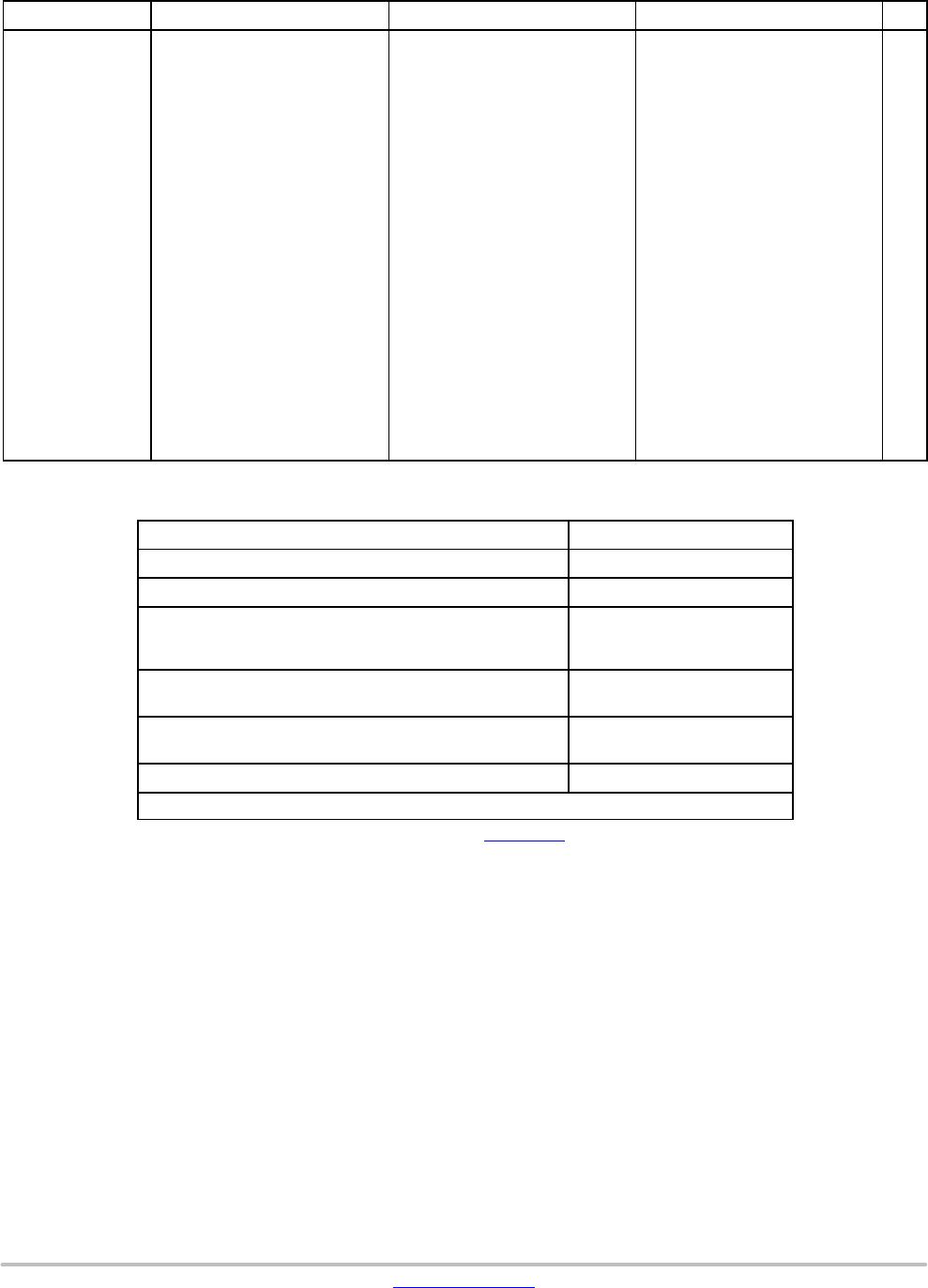
The MC10E/100E016 is a high-speed synchronous, presettable,
cascadable 8-bit binary counter. Architecture and operation are the
same as the MC10H016 in the MECL 10H™ family, extended to
8-bits, as shown in the logic symbol.
The counter features internal feedback of TC
, gated by the TCLD
(terminal count load) pin. When TCLD is LOW (or left open, in which
case it is pulled LOW by the internal pull-downs), the TC
feedback is
disabled, and counting proceeds continuously, with TC
going LOW to
indicate an all-one state. When TCLD is HIGH, the TC
feedback
causes the counter to automatically reload upon TC
= LOW, thus
functioning as a programmable counter. The Q
n
outputs do not need to
be terminated for the count function to operate properly. To minimize
noise and power, unused Q outputs should be left unterminated.
The 100 series contains temperature compensation.
Features
• 700 MHz Min. Count Frequency
• 1000 ps CLK to Q, TC
• Internal TC Feedback (Gated)
• 8-Bit
• Fully Synchronous Counting and TC Generation
• Asynchronous Master Reset
• PECL Mode Operating Range: V
CC
= 4.2 V to 5.7 V
with V
EE
= 0 V
• NECL Mode Operating Range: V
CC
= 0 V
with V
EE
= −4.2 V to −5.7 V
• These Devices are Pb-Free, Halogen Free and are RoHS Compliant
MARKING DIAGRAM*
xxx = 10 or 100
A = Assembly Location
WL = Wafer Lot
YY = Year
WW = Work Week
G = Pb-Free Package
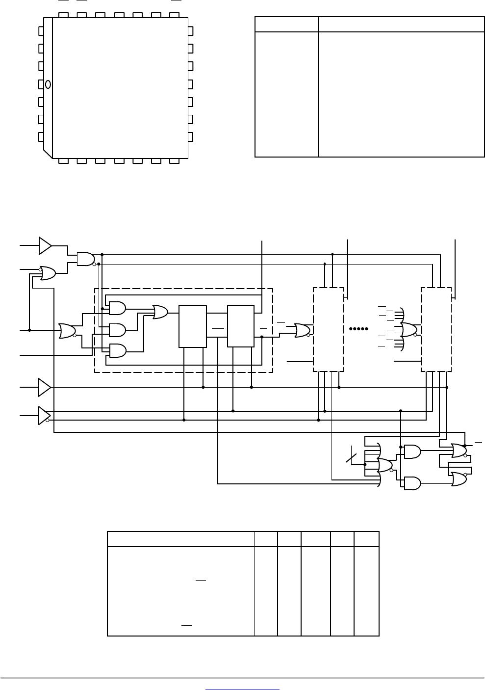
PLCC−28
FN SUFFIX
CASE 776−02
MCxxxE016G
AWLYYWW
1
www.onsemi.com
*For additional marking information, refer to
Application Note AND8002/D
.
†For information on tape and reel specifications, in-
cluding part orientation and tape sizes, please refer
to our Tape and Reel Packaging Specifications
Brochure, BRD8011/D
.
ORDERING INFORMATION
Device Package Shipping
MC10E016FNG PLCC−28
(Pb-Free)
37 Units/Tube
MC10E016FNR2G
500 Tape & Reel
MC100E016FNR2G
MC100E016FNG
PLCC−28
(Pb-Free)
PLCC−28
(Pb-Free)
PLCC−28
(Pb-Free)
37 Units/Tube
500 Tape & Reel