PTVA030121EA-V1-R0

4600 Silicon Drive | Durham, NC 27703 | www.wolfspeed.com
Rev. 06, 2018-06-13
7
PTVA030121EA
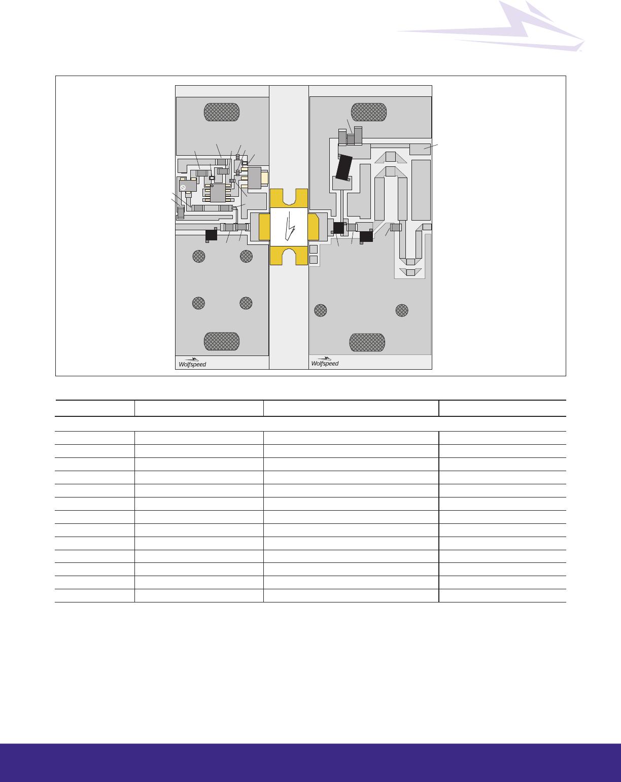
Reference circuit assembly diagram (not to scale)
Component ID Description Suggested Supplier P/N
Input
C101 Chip capacitor, 300 pF ATC ATC100B301JW200XB
C801, C802 Capacitor, 1000 pF Panasonic Electronic Components ECJ-1VB1H102K
L1 Inductor, 5 nH Coilcraft A02TGLB
R101 Resistor, 2.2 W Panasonic Electronic Components ERJ-8GEYJ2R2V
R102 Resistor, 1000 W Panasonic Electronic Components ERJ-8GEYJ102V
R801, R807 Resistor, 1200 W Panasonic Electronic Components ERJ-3GEYJ122V
R802 Resistor, 6200 W Panasonic Electronic Components ERJ-8GEYJ622V
R803 Resistor, 10 W Panasonic Electronic Components ERJ-8GEYJ100V
R804, R805, R808 Resistor, 2000 W Panasonic Electronic Components ERJ-8GEYJ202V
R806 Resistor, 1300 W Panasonic Electronic Components ERJ-3GEYJ132V
S1 Transistor Infineon Technologies BCP56
S2 Voltage regulator Fairchild Semiconductor LM7805CT
S3 Potentiometer, 2K W Bourns Inc. 3224W-1-202E
table continued next page
Reference Circuit (cont.)
Heat SInk
PTVA030121EA
Production and Customer Circuit
MWO Grey
Metal
PCB
PCB
Leads & Flange
PTFA 210452EF/LF
REFERENCE ON GRAPHIC:
a030121ea-v1_CD 10-13-2011
R802
RF_IN
R101
R805
R801
R804
R807
C801
R806
R808
R102
C101
a0 30 12 1e a- v 1_ C D 0 6-1 9- 2 01 8
L1
RO4350, .030 (60) RO4350, .030 (61)
PTVA030121_IN
PTVA030121_OUT
C201
C204
C202
C205
C203
RF_OUT
L1
L2
L3
VDD
R803
C802
S2
S3
S1
4600 Silicon Drive | Durham, NC 27703 | www.wolfspeed.com
Rev. 06, 2018-06-13
8
PTVA030121EA
Component ID Description Suggested Supplier P/N
Output
C201 Chip capacitor, 9.1 pF ATC ATC100B9R1BW500XB
C202 Chip capacitor, 300 pF ATC ATC100B301JW200XB
C203 Chip capacitor, 10 µF TDK Corporation C5750X7S2A106M230KB
C204 Capacitor, 1 µF TDK Corporation C4532X7R2A105K230KA
C205 Chip capacitor, 300 pF ATC ATC100B301JW200XB
L1, L2 Inductor, 8 nH Coilcraft A03TGLB
L3 Inductor, 43 nH Coilcraft B10TGLB
See next page for package mechanical specifications
Reference Circuit
(cont.)
4600 Silicon Drive | Durham, NC 27703 | www.wolfspeed.com
Rev. 06, 2018-06-13
9
PTVA030121EA
Package Outline Specifications
Package H-36265-2
2X 7.11
[.280]
45° X 2.03
[.080]
3.05
[.120]
C
L
C
L
FLANGE
9.78
[.385]
2X R1.52
[R.060]
4X R0.63
[R.025] MAX
6.
D
S
G
15.49±.51
[.610±.020]
4X R1.52
[R.060]
LID
10.16±.25
[.400±.010]
2.66±.51
[.105±.020]
ALL FOUR
CORNERS
15.23
[.600]
SPH 1.57
[.062]
20.31
[.800]
1.02
[.040]
10.16±.25
[.400±.010]
6.
3.61±.38
[.142±.015]
h - 3 6 2 6 5 - 2 _ p o _ 0 9 - 0 8 - 2 0 1 1
Diagram Notes—unless otherwise specified:
1. Interpret dimensions and tolerances per ASME Y14.5M-1994.
2. Primary dimensions are mm. Alternate dimensions are inches.
3. All tolerances ±0.127 [0.005] unless specified otherwise.
4. Pins: D – drain; G – gate; S – source
5. Lead thickness: 0.10 + 0.051/–0.025 mm [0.004 + 0.002/–0.001 inch].
6. Exposed metal plane on top and bottom of ceramic insulator.
7. Gold plating thickness: 1.14 ± 0.38 micron [45 ± 15 microinch].
Diagram Notes—unless otherwise specified:
1. Interpret dimensions and tolerances per ASME Y14.5M-1994.
2. Primary dimensions are mm. Alternate dimensions are inches.
3. All tolerances ± 0.127 [.005] unless specified otherwise.
4. Pins: D - drain, G - gate, S - source.
5. Lead thickness: 0.10 +0.051/–0.025 [.004 +.002/–.001].
6. Exposed metal plane on top and bottom of ceramic insulator.
7. Gold plating thickness: 1.14 ± 0.38 micron [45 ± 15 microinch].

PTVA030121EA-V1-R0

Mfr. #:
Manufacturer:
N/A
Description:
RF MOSFET Transistors RF LDMOS FET
Lifecycle:
New from this manufacturer.
Delivery:
DHL FedEx Ups TNT EMS
Payment:
T/T Paypal Visa MoneyGram Western Union

Products related to this Datasheet