AD620
Rev. H | Page 18 of 20
AD620ACHIPS INFORMATION
Die size: 1803 μm × 3175 μm
Die thickness: 483 μm
Bond Pad Metal: 1% Copper Doped Aluminum
To minimize gain errors introduced by the bond wires, use Kelvin connections between the chip and the gain resistor, R
G
, by connecting
Pad 1A and Pad 1B in parallel to one end of R
G
and Pad 8A and Pad 8B in parallel to the other end of R
G
. For unity gain applications
where R
G
is not required, Pad 1A and Pad 1B must be bonded together as well as the Pad 8A and Pad 8B.
1A
1B
2
3
4
5
6
7
8A
8B
LOGO
00775-0-053
Figure 49. Bond Pad Diagram
Table 6. Bond Pad Information
Pad Coordinates
1
Pad No. Mnemonic
X (μm) Y (μm)
1A R
G
−623 +1424
1B R
G
−789 +628
2 −IN −790 +453
3 +IN −790 −294
4 −V
S
−788 −1419
5 REF +570 −1429
6 OUTPUT +693 −1254
7 +V
S
+693 +139
8A R
G
+505 +1423
8B R
G
+693 +372
1
The pad coordinates indicate the center of each pad, referenced to the center of the die. The die orientation is indicated by the logo, as shown in Figure 49.
AD620
Rev. H | Page 19 of 20
OUTLINE DIMENSIONS
COMPLIANT TO JEDEC STANDARDS MS-001
CONTROLLING DIMENSIONS ARE IN INCHES; MILLIMETER DIMENSIONS
(IN PARENTHESES) ARE ROUNDED-OFF INCH EQUIVALENTS FOR
REFERENCE ONLY AND ARE NOT APPROPRIATE FOR USE IN DESIGN.
CORNER LEADS MAY BE CONFIGURED AS WHOLE OR HALF LEADS.
070606-A
0.022 (0.56)
0.018 (0.46)
0.014 (0.36)
SEATING
PLANE
0.015
(0.38)
MIN
0.210 (5.33)
MAX
0.150 (3.81)
0.130 (3.30)
0.115 (2.92)
0.070 (1.78)
0.060 (1.52)
0.045 (1.14)
8
1
4
5
0.280 (7.11)
0.250 (6.35)
0.240 (6.10)
0.100 (2.54)
BSC
0.400 (10.16)
0.365 (9.27)
0.355 (9.02)
0.060 (1.52)
MAX
0.430 (10.92)
MAX
0.014 (0.36)
0.010 (0.25)
0.008 (0.20)
0.325 (8.26)
0.310 (7.87)
0.300 (7.62)
0.195 (4.95)
0.130 (3.30)
0.115 (2.92)
0.015 (0.38)
GAUGE
PLANE
0.005 (0.13)
MIN
Figure 50. 8-Lead Plastic Dual In-Line Package [PDIP]
Narrow Body (N-8).
Dimensions shown in inches and (millimeters)
CONTROLLING DIMENSIONS ARE IN INCHES; MILLIMETER DIMENSIONS
(IN PARENTHESES) ARE ROUNDED-OFF INCH EQUIVALENTS FOR
REFERENCE ONLY AND ARE NOT APPROPRIATE FOR USE IN DESIGN.
0.310 (7.87)
0.220 (5.59)
0.005 (0.13)
MIN
0.055 (1.40)
MAX
0.100 (2.54) BSC
15°
0.320 (8.13)
0.290 (7.37)
0.015 (0.38)
0.008 (0.20)
SEATING
PLANE
0.200 (5.08)
MAX
0.405 (10.29) MAX
0.150 (3.81)
MIN
0.200 (5.08)
0.125 (3.18)
0.023 (0.58)
0.014 (0.36)
0.070 (1.78)
0.030 (0.76)
0.060 (1.52)
0.015 (0.38)
14
58
Figure 51. 8-Lead Ceramic Dual In-Line Package [CERDIP]
(Q-8)
Dimensions shown in inches and (millimeters)
CONTROLLING DIMENSIONS ARE IN MILLIMETERS; INCH DIMENSIONS
(IN PARENTHESES) ARE ROUNDED-OFF MILLIMETER EQUIVALENTS FOR
REFERENCE ONLY AND ARE NOT APPROPRIATE FOR USE IN DESIGN.
COMPLIANT TO JEDEC STANDARDS MS-012-AA
012407-A
0.25 (0.0098)
0.17 (0.0067)
1.27 (0.0500)
0.40 (0.0157)
0.50 (0.0196)
0.25 (0.0099)
45°
1.75 (0.0688)
1.35 (0.0532)
SEATING
PLANE
0.25 (0.0098)
0.10 (0.0040)
4
1
85
5.00 (0.1968)
4.80 (0.1890)
4.00 (0.1574)
3.80 (0.1497)
1.27 (0.0500)
BSC
6.20 (0.2441)
5.80 (0.2284)
0.51 (0.0201)
0.31 (0.0122)
COPLANARITY
0.10
Figure 52. 8-Lead Standard Small Outline Package [SOIC_N]
Narrow Body (R-8)
Dimensions shown in millimeters and (inches)
AD620
Rev. H | Page 20 of 20
ORDERING GUIDE
Model
1
Temperature Range Package Description Package Option
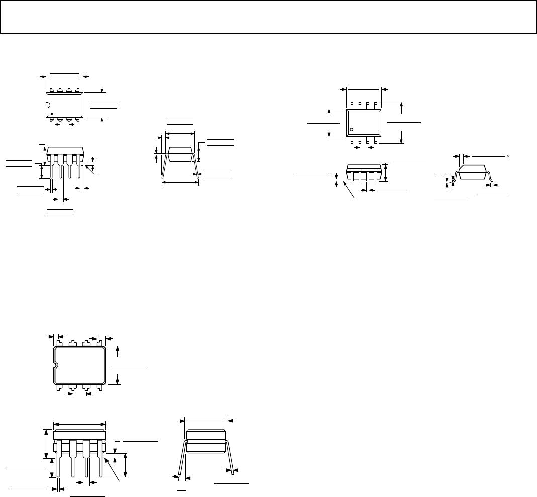
AD620AN −40°C to +85°C 8-Lead PDIP N-8
AD620ANZ −40°C to +85°C 8-Lead PDIP N-8
AD620BN −40°C to +85°C 8-Lead PDIP N-8
AD620BNZ −40°C to +85°C 8-Lead PDIP N-8
AD620AR −40°C to +85°C 8-Lead SOIC_N R-8
AD620ARZ −40°C to +85°C 8-Lead SOIC_N R-8
AD620AR-REEL −40°C to +85°C 8-Lead SOIC_N, 13" Tape and Reel R-8
AD620ARZ-REEL −40°C to +85°C 8-Lead SOIC_N, 13" Tape and Reel R-8
AD620AR-REEL7 −40°C to +85°C 8-Lead SOIC_N, 7" Tape and Reel R-8
AD620ARZ-REEL7 −40°C to +85°C 8-Lead SOIC_N, 7" Tape and Reel R-8
AD620BR −40°C to +85°C 8-Lead SOIC_N R-8
AD620BRZ −40°C to +85°C 8-Lead SOIC_N R-8
AD620BR-REEL −40°C to +85°C 8-Lead SOIC_N, 13" Tape and Reel R-8
AD620BRZ-RL −40°C to +85°C 8-Lead SOIC_N, 13" Tape and Reel R-8
AD620BR-REEL7 −40°C to +85°C 8-Lead SOIC_N, 7" Tape and Reel R-8
AD620BRZ-R7 −40°C to +85°C 8-Lead SOIC_N, 7" Tape and Reel R-8
AD620ACHIPS −40°C to +85°C Die Form
AD620SQ/883B −55°C to +125°C 8-Lead CERDIP Q-8
1
Z = RoHS Compliant Part.
© 2003–2011 Analog Devices, Inc. All rights reserved. Trademarks
and
registered trademarks are the property of their respective owners.
C00775–0–7/11(H)

AD620BRZ-R7

Mfr. #:
Manufacturer:
Analog Devices Inc.
Description:
Instrumentation Amplifiers AD620 Amplifier Low Drift Low Power
Lifecycle:
New from this manufacturer.
Delivery:
DHL FedEx Ups TNT EMS
Payment:
T/T Paypal Visa MoneyGram Western Union