MAX5943
FireWire Current Limiter and Low-Drop
ORing Switch Controller
______________________________________________________________________________________ 13
Timing accuracy is guaranteed for R
TIM
ranging from
4kΩ to 50kΩ. Large R
TIM
values can be used, which
reduces timing accuracy. A maximum timeout period is
enforced to prevent arbitrarily long operation in current-
limit/circuit-breaker conditions.
Long durations in current-limit/circuit-breaker mode
may produce excessive heating and electrical stresses
in R
SENSE
, Q1, Q2, and any other components in the
power path. Use component values rated to handle
electrical stresses during the timeout period.
Power-Supply ORing (ONQ1 = Low)
GATE1 controls the MAX5943 ORing function. The
MAX5943 accomplishes a very-low-voltage-drop diode
ORing function using an n-channel power MOSFET, Q1.
Initially, GATE1 is off (ONQ1 = low) and the load current
conducts through the body diode of Q1 (Figure 4).
GATE1 rises to 5.5V above SENSE when V
IS
exceeds
V
OR
, enhancing Q1. Q1’s low R
DS(ON)
provides a very-
low-voltage drop across its source to drain, reducing volt-
age drop, power dissipation, and heat generation in the
power-supply path created by a traditional diode.
The MAX5943 continuously monitors the load current
by the voltage drop, V
IS
, across the current-sensing
resistor. Q1 turns off rapidly when V
IS
decreases below
V
OR
minus its hysteresis.
Set the MAX5943 ORing threshold (V
OR
) by connecting
OR_ADJ to GND for a 5mV threshold, or to IN for a
10mV threshold, or leave it open for a 7.5mV threshold.
Connect ONQ1 to GND for normal ORing function.
Drive ONQ1 high to force Q1 on, regardless of the load
current condition, as long as the voltages at IN and ON
exceed V
UVLO
and V
ON_REF
, respectively, and the
device is not in a current fault shutdown.
When a higher voltage supply is connected at OUT
(Figure 5), the sense voltage drops below the program-
mable ORing threshold. The MAX5943 immediately
turns off Q1, blocking reverse current flow from OUT to
IN. The power is then routed from the higher supply
input to the load (Figure 6).
SENSE GATE1
OR_ADJ ONQ1GND
GATE2 OUT
Q1 Q2
IN
TO FireWire
PORT
MAX5943
ON
V
IN
R
SENSE
+ V
IS
-
Figure 4. Q1 Current Path During Inital Startup
I
LOAD
R
SENSE
SENSE GATE1
OR_ADJ ONQ1GND
GATE2 OUTIN
V
INA
V
INB
> V
INA
FROM
BATTERY
SOURCE
TO FireWire
PORT
I
INA
= 0
MAX5943
ON
R
SENSE
SENSE GATE1
OR_ADJ ONQ1GND
GATE2 OUTIN
V
INB
FROM
POWER
SOURCE
I
INB
MAX5943
ON
Figure 5. MAX5943 ORing Controller Rerouting Load Current
V
INA
I
INA
I
INB
V
INB
V
INB
> V
INA
V
OUT
Figure 6. MAX5943 Power Switch Over ORing Timing Diagram
MAX5943
FireWire Current Limiter and Low-Drop
ORing Switch Controller
14 ______________________________________________________________________________________
Reverse Current Override (ONQ1 = High)
Drive ONQ1 high to disable the power-supply ORing
function. Disabling the MAX5943 ORing function allows
reverse current flow through the power-supply system.
When ONQ1 is high, GATE1 remains fully enhanced as
long as V
IN
is greater than V
UVLO
, V
ON
is above the
V
ON_REF
threshold, and the MAX5943 is not in a cur-
rent-limit or circuit-breaker fault condition. The MAX5943
reverse-current flow feature permits a higher voltage
source connected to one port to route power to another
port, as long as the voltage at IN remains above the
minimum 7.5V operating range (see Figure 7).
Undervoltage Lockout
The MAX5943 operates from 7.5V to 37V and has a
default 6.5V undervoltage lockout threshold. The external
MOSFETs remain off as long as V
IN
> 6.5V and V
ON
<
V
ON_REF
. The turn-on threshold is programmable by
connecting a resistor-divider at ON. When V
ON
> 1.24V
and V
IN
> 7.5V, GATE2 is enhanced to 5.5V, with respect
to OUT and the MAX5943 goes into normal operation.
Program the MAX5943’s turn-on voltage using the fol-
lowing formula:
where V
TURN_ON
is the desired turn-on voltage of the
MAX5943. Choose an R2 value in the 1kΩ range to
minimize error due to the ON bias current.
When operating the MAX5943, ON must remain above
its 1.24V threshold. If V
ON
falls below its 1.24V thresh-
old, the power-supply MOSFETs (Q1 and Q2) turn off
immediately (less than 1µs). This allows the power sup-
ply to disconnect in the event of a fault condition
detected by the system, such as shorting of the output
to a different power-supply voltage or a FireWire signal
pin. If possible transient conditions exist at the main
power-supply line (IN), place an RC filter at ON to
reject transient voltage dips and to prevent unneces-
sary power-supply interruptions.
The MAX5943 remains in low-current shutdown mode
when V
ON
is below the 0.4V threshold. Low-current
shutdown mode disables the MAX5943 resulting in less
than 10µA supply current. Shutdown places all logic
inputs in a high-impedance state allowing the inputs to
be connected to IN without drawing additional current
from the supply. An internal delay, t
SD
, allows Q1 and
Q2 to be turned off before the MAX5943 enters low-
current shutdown mode.
Fault Status Output (FAULT)
FAULT is a high-voltage open-drain output that pulls low
when a current-limit/circuit-breaker fault shutdown has
occurred. FAULT remains low until the next startup cycle.
R
V
R
TURN ON
1
124
12=−
×
_
.
SENSE GATE1
OR_ADJGNDLATCHILIM
GATE2
PORT1
OUTIN
MAX5943
TIM
ON
ONQ1
FAULT
SENSE GATE1
OR_ADJGNDLATCHILIM
GATE2
PORT2
OUTIN
MAX5943
TIM
ON
ONQ1
FAULT
Figure 7. MAX5943 Operating in Reverse-Current Mode
(Routing Power from Port 1 to Port 2)
MAX5943
R2
R1
V
IN
IN
GND
ON
Figure 8. Setting the MAX5943 Turn-On Voltage
MAX5943
R2
R1
V
IN
IN
LATCH
GND
ON
Figure 9. Resetting MAX5943 After a Latched Fault Condition
MAX5943
FireWire Current Limiter and Low-Drop
ORing Switch Controller
______________________________________________________________________________________ 15
Fault Management
The MAX5943 offers either latch or autoretry fault man-
agement configurable by the LATCH input. Connect
LATCH to IN for latch fault management or connect
LATCH to GND for autoretry fault management. In latch
fault management, FAULT latches low, GATE1 and
GATE2 latch off indefinitely. Cycle ON low and then
high to unlatch and restart the MAX5943. However, the
MAX5943 will not enter a startup cycle until t
OFF
has
expired. Figure 9 illustrates a way to reset the MAX5943
after a fault using a pushbutton switch.
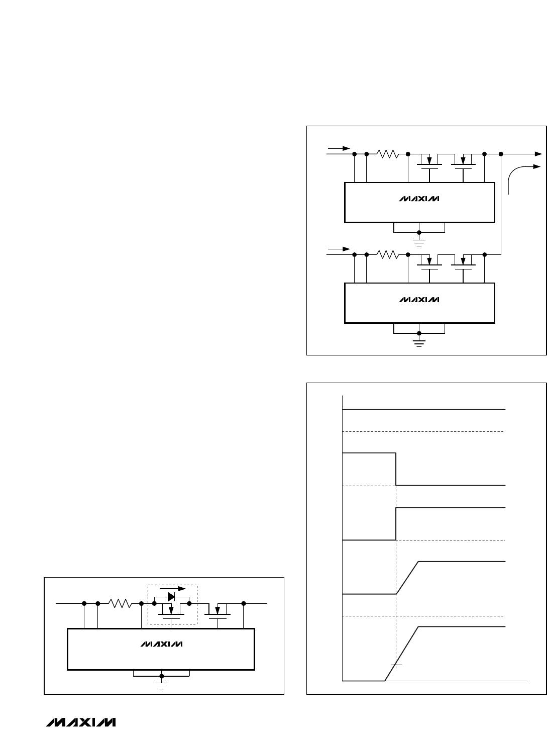
In autoretry fault management, the MAX5943_ attempt
to restart after a t
OFF
of 128 x t
ILIM
(or 128 x t
CB
) limit-
ing the duty cycle of the MOSFETs to 1/129 under con-
tinuous fault conditions. FAULT deasserts every time a
restart attempt is made.
Applications Information
Startup Consideration
MAX5943A
During startup, a large capacitor at OUT may result in a
charging current equivalent to the current limit. Choose a
current-limit timeout that will allow a successful startup.
The timeout can be approximated using the following
equation:
\where I
LIMIT
is the programmed current limit, C
OUT
is
the capacitor at OUT, V
IN
is the supply voltage, and
I
LOAD
is the load current during startup. With IN = 12V,
C
OUT
= 330µF, I
LIMIT
= 1.5A, and I
LOAD
= 0, the
MAX5943 commences by charging the output capacitor
with 1.5A for approximately 2.7ms. Therefore, the
MAX5943A current-limit timeout period (t
ILIM
) should be
greater than 2.7ms for a successful startup. Otherwise,
the MAX5943A powers up in fault management mode
by exceeding the current-limit timeout period.
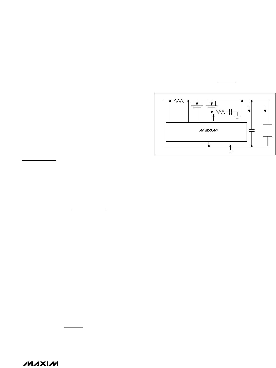
MAX5943B–MAX5943E
The MAX5943B–MAX5943E do not control the inrush
current during startup. Inrush current control can be
implemented by placing a resistor and capacitor at
GATE2 (Figure 10) to slowly ramp up the gate voltage,
thus limiting the inrush current. The inrush current can
be approximated using the following formula:
Where I
G2U
is GATE2’s 45µA sourcing current and
I
LOAD
is the load current at startup.
To prevent the MAX5943B–MAX5943E from starting up
in a fault condition set:
Optimizing for Short-Circuit Conditions
Choosing R
SENSE
Select a sense resistor that causes the circuit-breaker
voltage drop at a current-limit/circuit-breaker level
above the maximum normal operating current.
Typically, set the overload current at 1.2 to 1.5 times
the full load current.
Choose the sense-resistor power rating to accommodate
an overcurrent condition:
P
RSENSE
= I
2
LIMIT
x R
SENSE
where P
RSENSE
is the power dissipated across R
SENSE
during a current-limit/circuit-breaker fault.
Under short-circuit conditions, it is imperative that the
appropriate sense resistor is utilized. Operating the
MAX5943B–MAX5943E at high input voltages can
cause very large currents during the circuit-breaker
timeout period. The peak current will be limited by the
saturation current of Q2 or the series resistance in the
power path (R
TOTAL
).
Using a 30mΩ on-resistance MOSFET at GATE1 and
GATE2 and a 30mΩ sense resistor results in a short-cir-
cuit current approximately equal to:
I
SC
= V
IN
/R
TOTAL
where:
R
TOTAL
= R
SENSE
+ 2 x (R
ON
)
= 30mΩ + 2 x (30mΩ) = 90mΩ
For example, an input voltage of 20V produces a current
at approximately 222A (or I
SAT
of Q2, whichever is less)
in the power path for the circuit-breaker timeout period.
Choose an R
SENSE
capable of handling the high power
dissipation during a short-circuit event.
I
V
R
INRUSH
TH
SENSE
<
I
C
C
II
INRUSH
OUT
GATE
G U LOAD
+
2
2
t
CV
II
ILIM
OUT IN
LIMIT LOAD
>
×
Q1 Q2
C
GATE
C
OUT
R
SENSE
SENSE GATE1 GATE2
GND
OUT
LOAD
45μA
IN
+
-
V
IN
I
C
I
LOAD
MAX5943B–MAX5943E
1kΩ
Figure 10. Controlling the MAX5943B–MAX5943E Inrush Current

MAX5943CEEE+

Mfr. #:
Manufacturer:
Maxim Integrated
Description:
Hot Swap Voltage Controllers FireWire Current Limiter
Lifecycle:
New from this manufacturer.
Delivery:
DHL FedEx Ups TNT EMS
Payment:
T/T Paypal Visa MoneyGram Western Union