MAX5943
FireWire Current Limiter and Low-Drop
ORing Switch Controller
4 _______________________________________________________________________________________
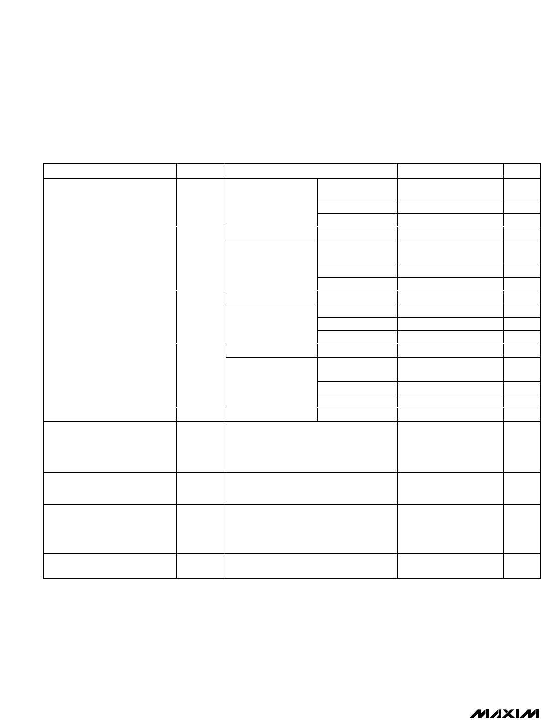
ELECTRICAL CHARACTERISTICS (continued)
(V
IN
= 7.5V to 37V, GND = 0V, and T
A
= -40°C to +85°C, unless otherwise noted. Typical values are at V
IN
= 12V, T
A
= +25°C.)
(Note 1)
PARAMETER SYMBOL CONDITIONS MIN TYP MAX UNITS
TIM = IN or
TIM ≥ 3.4V
0.45 0.51 0.57 ms
R
TIM
= 4kΩ 27 32.5 38 µs
R
TIM
= 50kΩ 228 345 403 µs
Circuit-breaker mode,
MAX5943B
TIM = floating 3.75 5.5 7 ms
TIM = IN or
TIM ≥ 3.4V
0.89 1.00 1.13 ms
R
TIM
= 4kΩ 54 65 76 µs
R
TIM
= 50kΩ 575 690 806 µs
Circuit-breaker mode,
MAX5943C
TIM = floating 7.5 10.9 14 ms
TIM = IN 1.78 2.02 2.26 ms
R
TIM
= 4kΩ 109 130 151 µs
R
TIM
= 50kΩ 1.15 1.38 1.61 ms
Circuit-breaker mode,
MAX5943D
TIM = floating 15 21.9 28 ms
TIM = IN or
TIM ≥ 3.4V
3.56 4.05 4.52 ms
R
TIM
= 4kΩ 217 260 303 µs
R
TIM
= 50kΩ 2.3 2.76 3.23 ms
Circuit-Breaker Timeout
(MAX5943B–MAX5943E) (Note 7)
t
CB
Circuit-breaker mode,
MAX5943E
TIM = floating 30 44 56 ms
Automatic Restart Delay After
Current-Limit/Circuit-Breaker
Timeout
t
OFF
LATCH = GND (Note 8)
128 x
(t
ILIM
OR
t
CB
ms
GATE1 Turn-Off Time
(ORing Response Time)
t
OR
From V
OR
trigger until (V
GATE1
- V
IN
) < 1V,
C
GATE1
= 10nF
100 ns
Turn-Off Response Time t
ON_OFF
Time from V
ON
< (V
ON_OFF
- Hysteresis)
until (V
GATE2
- V
OUT
) < 1V, GATE2 = open
(Note 9)
0.34 0.6 µs
Minimum Delay from ON Low to
Low-Current Shutdown Mode
t
SD
ON step from 1.3V to 0.4V 50 µs
Note 1: All min/max parameters are tested at +25°C and +85°C. Limits at -40°C are guaranteed by design.
Note 2: Measured at both V
GATE2
= V
OUT
= 0V and V
GATE2
= V
OUT
= V
IN
.
Note 3: The typical value of parameter V
THF
is 1.5 x V
TH
.
Note 4: Current-Limit/Circuit-Breaker Timeout; IN or ON low.
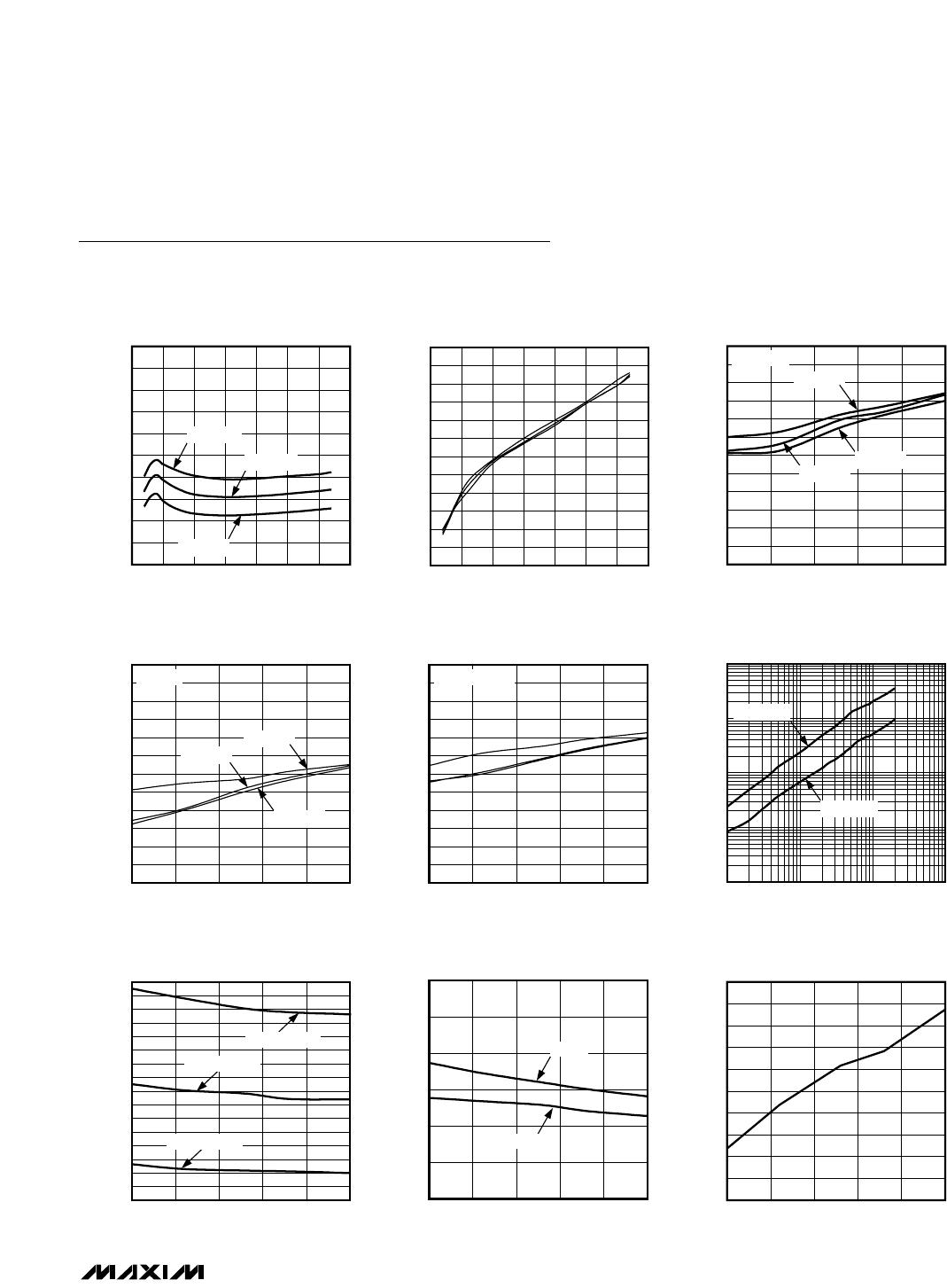
Note 5: See the
Typical Operating Circuit
. Measured at V
GATE1
= V
SENSE
.
Note 6: The tristate (“floating”) logic condition will be entered if the pin current is within these limits.
Note 7: R
TIM
is connected from TIM to GND. The maximum timeout period is enforced to prevent arbitrarily long operation in cur-
rent-limit mode. Therefore, the relationship between resistor value and timeout changes for large values of R
TIM
. See
Current-Limit Timeout vs. R
TIM
in the
Typical Operating Characteristics
for nominal values.
Note 8: Parameter t
OFF
is a direct multiple of t
ILIM
(or t
CB
), so the limits for t
OFF
track the limits for t
ILIM
(or t
CB
).
Note 9: If the ON voltage goes below V
ON_REF
- Hysteresis, then GATE2 goes low immediately to disconnect power from the load
quickly (within t
ON_OFF
).