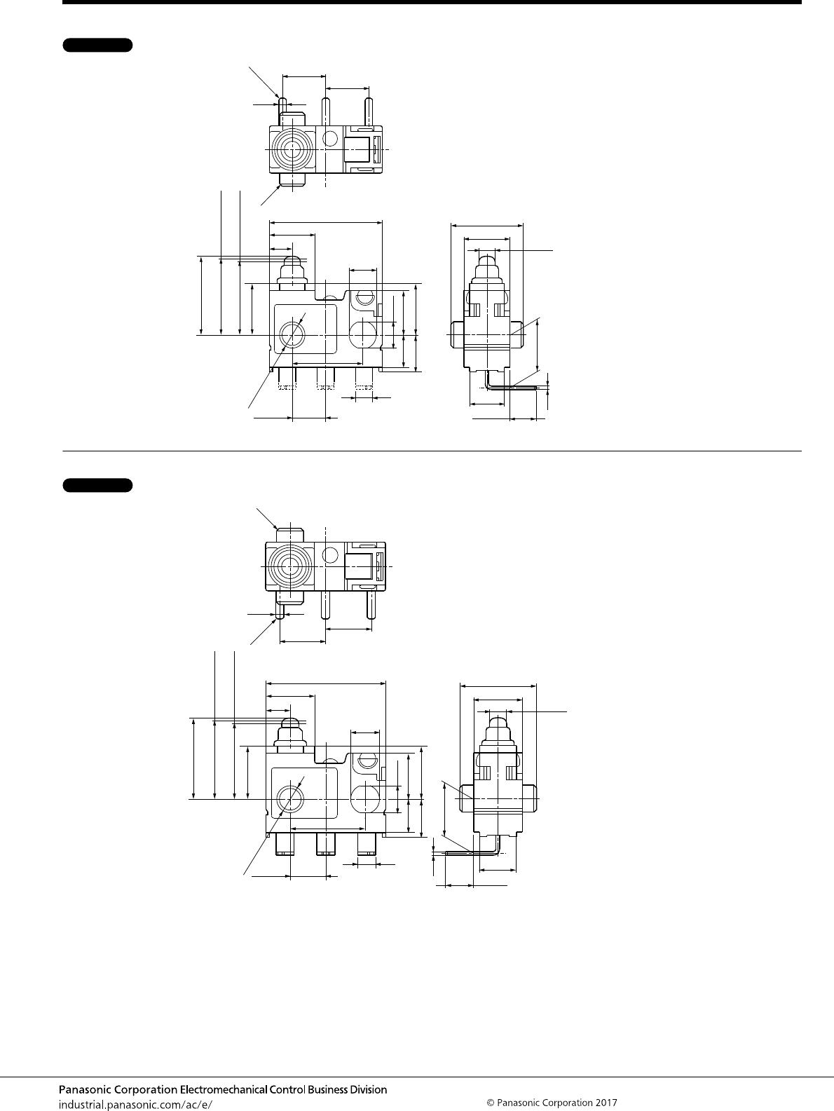
Turquoise Stroke Switches (ASQ1)
–9–
AECTB6E 201701-T
CAUTIONS FOR USE
■ Soldering conditions
The application of excessive heat upon
the switch when soldering can cause
degradation of switch operation.
Therefore, be sure to keep within the
conditions given below.
Manual soldering: use soldering irons
(max. 350°C, within 3 seconds at each
terminal) capable of temperature
adjustment. This is to prevent
deterioration due to soldering heat. Care
should be taken not to apply force to the
terminals during soldering.
(More than one second interval is
required to apply heat at each terminal.)
Please consult us if you intend to use a
soldering iron that exceeds 60 W.
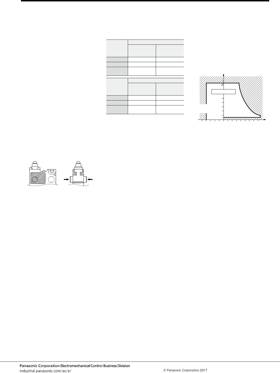
■ Mounting
Please avoid use in which load would be
applied to the sides (hatch part (both
sides) shown below) of the switch in the
direction indicated by the arrows. This
could cause erroneous operation. Also,
when using a metal installation board,
please make allowance for burr direction
designation and burr suppressing, etc.,
so that the burr side will not be on the
switch installation side.
1) To secure the switch, please use an
M3 small screw on a flat surface and
tighten using a maximum torque of 0.29
N·m. It is recommended that both flat
metal washer and spring washers be
used with the screws and adhesive be
applied to lock the screws to prevent
loosening of the screws. Please make
sure not to apply adhesive onto the
moving parts.
2) Be sure to maintain adequate
insulating clearance between each
terminal and ground.
3) Although it is possible to directly
operate the pin plunger type from the
lateral direction, please consult us if
doing so.
4) After mounting please make sure no
tensile load will be applied to the switch
terminals.
5) Range of possible use: Please set the
operation position to within the ranges in
the following table so that there is
sufficient insulation distance and to
maintain contact reliability.
6) PC board terminal type should be
used if the products are to be soldered on
the PC board. Solder terminal type is not
for soldering on PC board.
■ Cautions regarding the circuit
1) In order to prevent malfunction in set
devices caused by bounce and chattering
during the ON-OFF switch operation,
please verify the validity of the circuit
under actual operating conditions and
temperature range.
2) When switching inductive loads
(relays, solenoids, buzzers, etc.), an arc
absorbing circuit is recommended to
protect the contacts.
■ Please verify under actual
conditions.
Please be sure to conduct quality
verification under actual operating
conditions in order to increase reliability
during actual use.
■ Selection of switch
Please make your selection so that there
will be no problems even if the operating
characteristics vary up to ±20% from the
standard values.
■ Oil-proof and chemical-proof
characteristics
Do not use alcohol-based solvents.
The rubber cap swells when exposed to
oil and chemicals. The extent of swelling
will vary widely depending on the type
and amount of oil and chemicals.
Check with the actual oil or chemicals
used. In particular, be aware that solvents
such as freon, chlorine, toluene, and
cannot be used.
■ Environment
1) Although continuous operation of the
switch is possible within the range of
ambient temperature (humidity), as the
humidity range differs depending on the
ambient temperature, the humidity range
indicated below should be used.
Continuous use near the limit of the
range should be avoided.
2) This humidity range does not
guarantee permanent performance.
■ Other
Be careful when handling the switch to
make sure that the rubber cap for sealing
the plunger does not break.
1) Please remember that this switch
cannot be used under water. Also, please
be warned that switching and sudden
temperature changes with the presence
of water droplets can cause seepage into
the switch.
2) Keep away from environments where
silicon based adhesives, oil or grease are
present as faulty contacts may result
from silicon oxide. Do not use in areas
where flammable or explosive gases from
gasoline and thinner, etc., may be
present.
3) When using the lever type, please be
careful not to apply unreasonable load
from the reverse or lateral directions of
operation.
4) Do not exceed the total travel position
(TTP) and press the actuator. This could
cause operation failure. Also, when
switching at high speed or under shock
even within the operation limit, the
working life may decrease. Therefore,
please be sure to verify the quality under
actual conditions of use.
5) Please make considerations so that
the switch does not become the stopper
for the moving part.
6) Please do not pull wire leads
constantly.
Actuator
Plunger/lever free
From mounting
boss and hole
center line
From standoff
Pin plunger >9.2 mm >13.4 mm
Leaf lever >10.7 mm >14.9 mm
Simulated
leaf lever
>13.5 mm >17.7 mm
Actuator
Plunger/Lever pushed
From mounting
boss and hole
center line
From standoff
Pin plunger 7.8 to 5.9 mm 12.0 to 10.1 mm
Leaf lever 8.4 to 6.2 mm 12.6 to 10.4 mm
Simulated
leaf lever
11.1 to 8.7 mm 15.3 to 12.9 mm
Acceptable range
(Avoid
condensation when
used at temperatures
higher than 0°C)
(Avoid freezing when
used at temperatures
lower than 0°C)
95
50
5
–40 0 +85
Temperature, °C
Humidity, %R.H.