XR33180/81/83/84
9/12
REV1B
Applications Information (Continued)
The XR3318x RS-485/RS-422 device is part of Exar’s high performance serial interface product line. The analog bus pins
can survive direct shorts up to ±18V and are protected against ESD events up to ±15kV.
Enhanced Failsafe
Ordinary RS-485 differential receivers will be in an indeterminate state whenever the data bus is not being actively driven.
The enhanced failsafe feature of the XR3318x guarantees a logic-high receiver output when the receiver inputs are open,
shorted or when they are connected to a terminated transmission line with all drivers disabled. In a terminated bus with all
transmitters disabled, the receivers’ differential input voltage is pulled to 0V by the termination. The XR3318x interprets 0V
differential as a logic high with a minimum 50mV noise margin while maintaining compliance with the RS-485 standard of
±200mV. Although the XR3318x does not need failsafe biasing resistors, it can operate without issue if biasing is used.
±15kV ESD Protection
ESD protection structures are incorporated on all pins to protect against electrostatic discharges encountered
during handling and assembly. The receiver inputs of the XR3318x have extra protection against static
electricity. Exar uses state-of-the-art structures to protect these pins against ESD of ±15kV without damage.
The ESD structures withstand high ESD in all states: normal operation and powered down. After an ESD event, the XR3318x
keeps operating without latch-up or damage.
ESD protection can be tested in various ways. The receiver inputs of the XR3318x are characterized for protection to the
following limits:
±15kV HBM (Human Body Model), bus pins
±15kV IEC 61000-4-2 air discharge, bus pins
±8kV IEC 61000-4-2 contact discharge, bus pins
±4kV using the Human Body Model, all other pins
ESD Test Conditions
ESD performance depends on a variety of conditions. Contact Exar for a reliability report that documents test setup,
methodology and results.
Maximum Number of Receivers on the Bus
The standard RS-485 receiver input impedance is 12kΩ (1 unit load). A standard driver can drive up to 32 unit loads. The
XR3318x receiver has a 1/4th unit load receiver input impedance of 48KΩ, allowing up to 128 receivers to be connected in
parallel on a communication line. Any combination of the XR33180/81/83/84’s and other RS-485 receivers up to a total of
32 unit loads may be connected to the line.
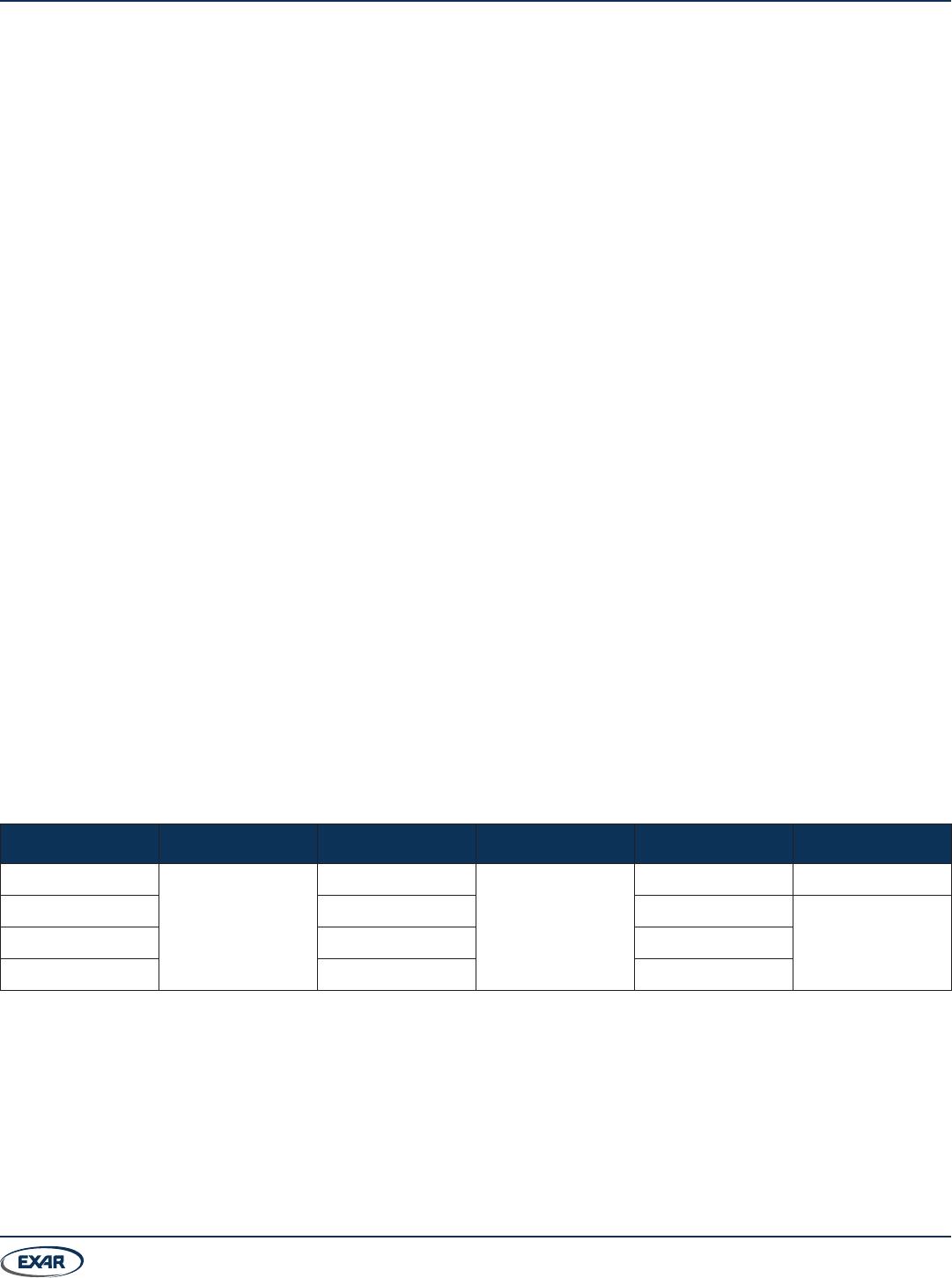
Product Selector Guide
Part Number Data Rate Receiver Enable Nodes On Bus V
L
Pin Package
XR33180
52Mbps
No
128
No 5-pin TSOT23
XR33181 Yes (active high) No
6-pin TSOT23XR33183 Yes (active low) No
XR33184 No Yes