© Semiconductor Components Industries, LLC, 2012
June, 2018 − Rev. 9
1 Publication Order Number:
CAT25080/D
CAT25080, CAT25160
EEPROM Serial 8/16-Kb SPI
Description
The CAT25080/25160 are a EEPROM Serial 8/16−Kb SPI devices
internally organized as 1024x8/2048x8 bits. They feature a 32−byte
page write buffer and support the Serial Peripheral Interface (SPI)
protocol. The device is enabled through a Chip Select (CS) input. In
addition, the required bus signals are a clock input (SCK), data input
(SI) and data output (SO) lines. The HOLD
input may be used to pause
any serial communication with the CAT25080/25160 device. These
devices feature software and hardware write protection, including
partial as well as full array protection.
Features
• 20 MHz SPI (5 V) Compatible
• 1.8 V to 5.5 V Supply Voltage Range
• SPI Modes (0,0) & (1,1)
• 32−byte Page Write Buffer
• Self−timed Write Cycle
• Hardware and Software Protection
• Block Write Protection
− Protect 1/4, 1/2 or Entire EEPROM Array
• Low Power CMOS Technology
• 1,000,000 Program/Erase Cycles
• 100 Year Data Retention
• Industrial and Extended Temperature Range
• 8−lead SOIC, TSSOP and 8−pad, UDFN Packages
• These Devices are Pb−Free, Halogen Free/BFR Free, and RoHS
Compliant
SI
SO
CAT25080
CAT25160
SCK
V
SS
V
CC
CS
WP
HOLD
Figure 1. Functional Symbol
www.onsemi.com
PIN CONFIGURATION
SI
HOLD
V
CC
V
SS
WP
SO
CS
1
See detailed ordering and shipping information in the package
dimensions section on page 11 of this data sheet.
ORDERING INFORMATION
SOIC−8
V SUFFIX
CASE 751BD
SCK
SOIC (V), TSSOP (Y), UDFN (HU2, HU4)
TSSOP−8
Y SUFFIX
CASE 948AL
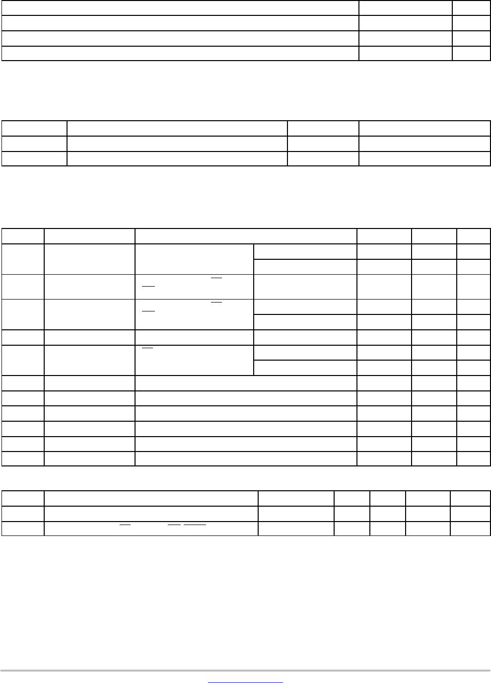
Chip SelectCS
Serial Data OutputSO
Write ProtectWP
GroundV
SS
Serial Data InputSI
Serial ClockSCK
FunctionPin Name
†
PIN FUNCTION
Hold Transmission InputHOLD
Power SupplyV
CC
UDFN−8
HU4 SUFFIX
CASE 517AZ
†The exposed pad for the UDFN packages can be left
floating or connected to Ground.