81006 DATA SHEET
VCXO-TO-6 LVCMOS OUTPUTS 10 REVISION B 7/29/16
Applications Information
VCXO Crystal Selection
Choosing a crystal with the correct characteristics is one of the most
critical steps in using a Voltage Controlled Crystal Oscillator (VCXO).
The crystal parameters affect the tuning range and accuracy of a
VCXO. Below are the key variables and an example of using the
crystal parameters to calculate the tuning range of the VCXO.
Oscillator
VCXO (Internal)
C
V
Optional
C
V
C
S1
C
S2
C
L1
C
L2
V
C
“Control Voltage”
XTAL
Figure 1. VCXO Oscillator Circuit
V
C
-Control voltage used to tune frequency
C
V
-Varactor capacitance, varies due to the change in control voltage
C
L1
C
L2
-Load tuning capacitance used for fine tuning or centering nominal frequency
C
S1
C
S2
-Stray Capacitance caused by pads, vias, and other board parasitics
Table 5. Example Crystal Parameters
Symbol Parameter Test Conditions Min Typical Max Units
f
N
Nominal Frequency 19.44 MHz
f
T
Frequency Tolerance ±20 ppm
f
S
Frequency Stability ±20 ppm
Operating Temp Range 0 70 °C
C
L
Load Capacitance 12 pF
C
O
Shunt Capacitance 4 pF
C
O
/C
1
Pullability Ratio 220 240
ESR Equivalent Series Resistance 20
Drive Level 1 mW
Aging @ 25°C ±3 per year ppm
Mode of Operation Fundamental
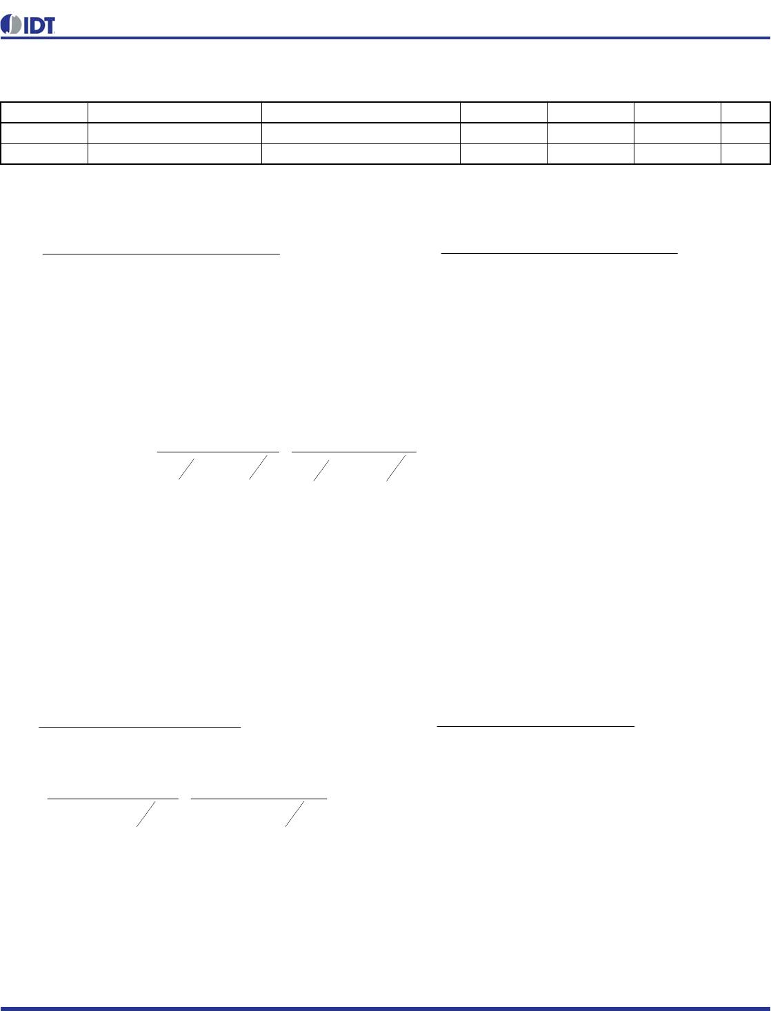
Table 6. Varactor Parameters
Test Condition Minimum Typical Maximum Unit
C
V_LOW
Low Varactor Capacitance V
C
= 0V 15.4 pF
C
V_HIGH
High Varactor Capacitance V
C
= 3.3V 29.6 pF
REVISION B 7/29/16 11 VCXO-TO-6 LVCMOS OUTPUTS
81006 DATA SHEET
Formulas
•C
Low
is the effective capacitance due to the low varactor capacitance, load capacitance and stray capacitance.
C
Low
determines the high frequency component on the TPR.
•C
High
is the effective capacitance due to the high varactor capacitance, load capacitance and stray capacitance.
C
High
determines the low frequency component on the TPR.
Absolute Pull Range (APR) = Total Pull Range – (Frequency Tolerance + Frequency Stability + Aging)
Example Calculations
Using the tables and figures above, we can now calculate the TPR
and APR of the VCXO using the example crystal parameters. For the
numerical example below there were some assumptions made. First,
the stray capacitance (C
S1
, C
S2
), which is all the excess capacitance
due to board parasitic, is 4pF. Second, the expected lifetime of the
project is 5 years; hence the inaccuracy due to aging is ±15ppm.
Third, though many boards will not require load tuning capacitors
(C
L1
, C
L2
), it is recommended for long-term consistent performance
of the system that two tuning capacitor pads be placed into every
design. Typical values for the load tuning capacitors will range from 0
to 4 pF.


pf
pfpfpfpf
pfpfpfpf
C
Low
7.9
4.15404.1540
4.15404.1540


pf
pfpfpfpf
pfpfpfpf
C
High
8.16
6.29406.2940
6.29406.2940
ppm
pF
pF
pF
pF
TPR 5.22610
4
8.16
12202
1
4
7.9
12202
1
6
TPR = ±113.25ppm
APR = 113.25ppm – (20ppm + 20ppm + 15ppm) = ±58.25ppm
The example above will ensure a total pull range of ±113.25 ppm with
an APR o
f ±58.25ppm. Many times, board designers may select their
own crystal based on their application. If the application requires a
tighter APR, a crystal with better pullability (C0/C1 ratio) can be used.
Also, with the equations above, one can vary the frequency tolerance,
temperature stability, and aging or shunt capacitance to achieve the
required pullability.
Symbol Parameter


LowVSLLowVSL
LowVSLLowVSL
Low
CCCCCC
CCCCCC
C
_22_11
_22_11


HighVSLHighVSL
HighVSLHighVSL
High
CCCCCC
CCCCCC
C
_22_11
_22_11
6
01
0
01
0
10
12
1
12
1
)(
C
C
C
C
C
C
C
C
TPRRangePullTotal
HighLow
81006 DATA SHEET
VCXO-TO-6 LVCMOS OUTPUTS 12 REVISION B 7/29/16
Recommendations for Unused Input Pins
Inputs:
Control Pins
All control pins have internal pull-ups or pull-downs; additional
resistance is not required but can be added for additional protection.
A 1kresistor can be used. The VC pin can not be floated.
Outputs:
LVCMOS Outp
uts
All unused LVCMOS output can be left floating. We recommend
that there is no trace attached.
Schematic Example
Figure 2 shows an example of 81006 application schematic. The
decoupling capacitors should be located as close as possible to the
po
wer pin. For the LVCMOS 20
output drivers, series termination
example is shown in the schematic. Additional termination
approaches are shown in the LVCMOS Termination Application Note.
C2
SPARE
R5 1K
VC = 0V to VDD
VDD
C1
SPARE
U1
81006
2
3
4
5
6
7
8
9
11
12
13
14
17
18
19
20
10 16
151
XTAL_OUT
VDD
VC
DIV_SEL_Q5
OE1
GND
Q5
VDDO
GND
Q3
VDDO
Q2
VDDO
Q0
GND
OE0
Q4 Q1
GNDXTAL_IN
Zo = 50
(U1-13)
C3
0.1uF
Unused outputs can be left floating. There should be
no trace attached to unused outputs. Device
characterized and specification limits set with all
outputs terminated.
C6
0.1uF
C5
0.1uF
C7
10uf
Pull-up
example
(U1-9)
R4
1K
Quartz crystal should be
placed as close to the
device as possible.
VDDO
Pull-down
example
VDD
R3
1K
VDDO
R1
30
VDD
R2
30
VC
C4
0.1uF
XTAL
(U1-17)
Zo = 50
VDD
(U1-3)
Figure 2. 81006 Schematic Example

81006AKLFT

Mfr. #:
Manufacturer:
IDT
Description:
Clock Generators & Support Products 6 CMOS OUT VCXO
Lifecycle:
New from this manufacturer.
Delivery:
DHL FedEx Ups TNT EMS
Payment:
T/T Paypal Visa MoneyGram Western Union

Products related to this Datasheet