OP400 Data Sheet
Rev. H | Page 12 of 16
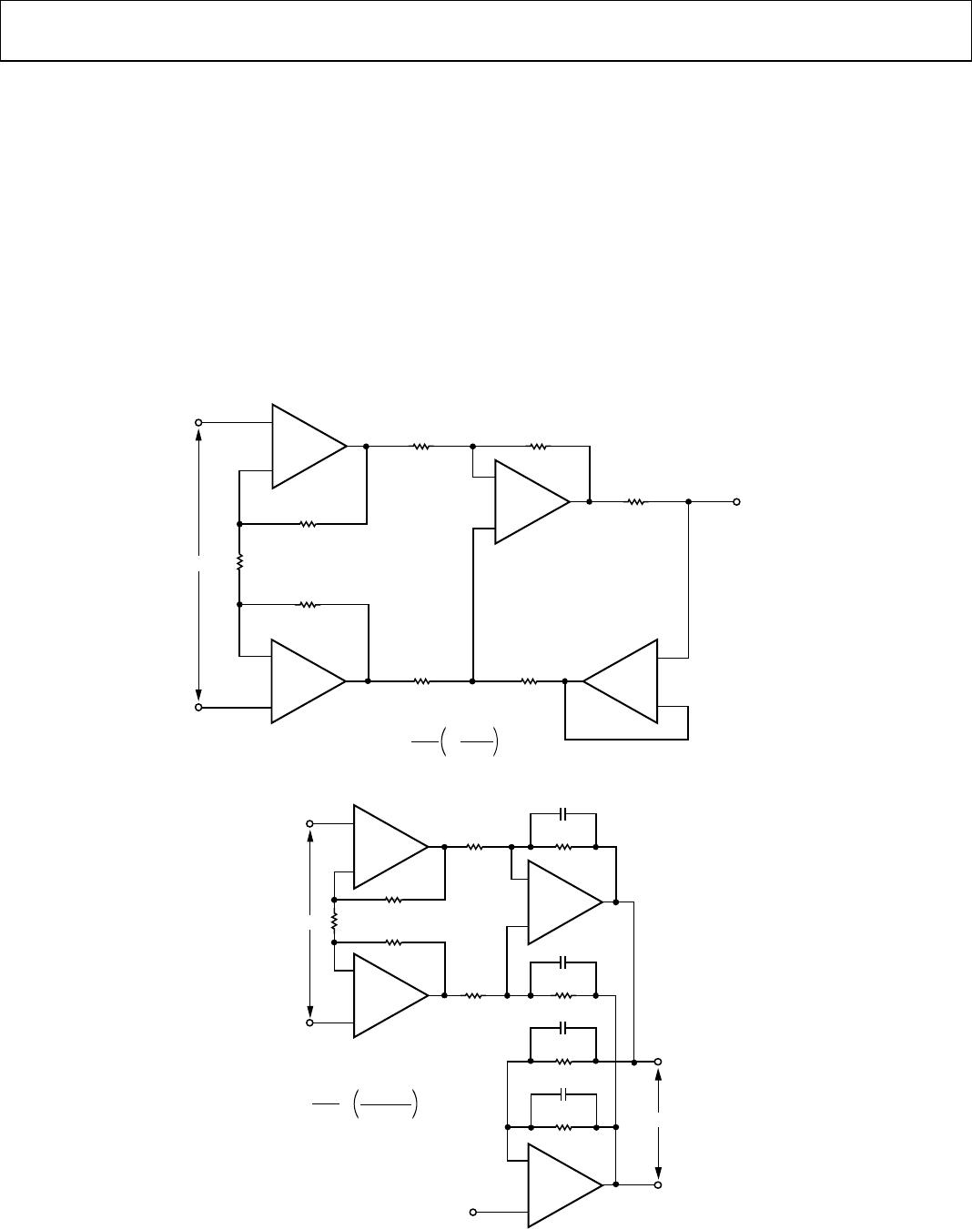
BIPOLAR CURRENT TRANSMITTER
In the circuit of Figure 32, which is an extension of the standard
three op amp instrumentation amplifier, the output current is
proportional to the differential input voltage. Maximum output
current is ±5 mA, with voltage compliance equal to ±10 V when
using ±15 V supplies. Output impedance of the current
transmitter exceeds 3 MΩ, and linearity is better than 16 bits
with gain set for a full-scale input of ±100 µV.
DIFFERENTIAL OUTPUT INSTRUMENTATION
AMPLIFIER
The output voltage swing of a single-ended instrumentation
amplifier is limited by the supplies, normally at ±15 V, to
a maximum of 24 V p-p. The differential output instrumenta-
tion amplifier shown in Figure 33 can provide an output voltage
swing of 48 V p-p when operated with ±15 V supplies. The
extended output swing is due to the opposite polarity of the
outputs. Both outputs swing 24 V p-p, but with opposite
polarity, for a total output voltage swing of 48 V p-p. The reference
input can be used to set a common-mode output voltage over the
range ±10 V. The PSRR of the amplifier is less than 1 µV/V with
CMRR (G = 1000) better than 115 dB. Offset voltage drift is
typically 0.4 µV/°C over the military temperature range.
00304-031
–
+
V
OUT
I
OUT
5mA
I
OUT
V
IN
50,000
200Ω
200Ω
R
G
25kΩ
25kΩ
25kΩ 25kΩ
25kΩ 25kΩ
R
G
– –
1
V
IN
1/4
OP400E
+
–
1/4
OP400E
+
–
1/4
OP400E
+
–
1/4
OP400E
+
–
Figure 32. Bipolar Current Transmitter
–
+
00304-032
V
OUT
V
IN
R
G
25kΩ
25kΩ
25kΩ
25kΩ
25kΩ
22pF
22pF
22pF
22pF
25kΩ
25kΩ
25kΩ
V
OUT
V
IN
=
50kΩ + R
G
R
G
REFERENCE
INPUT
1/4
OP400A
+
–
1/4
OP400A
+
–
1/4
OP400A
+
–
1/4
OP400A
+
–
Figure 33. Differential Output Instrumentation Amplifier

