4
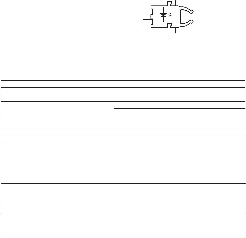
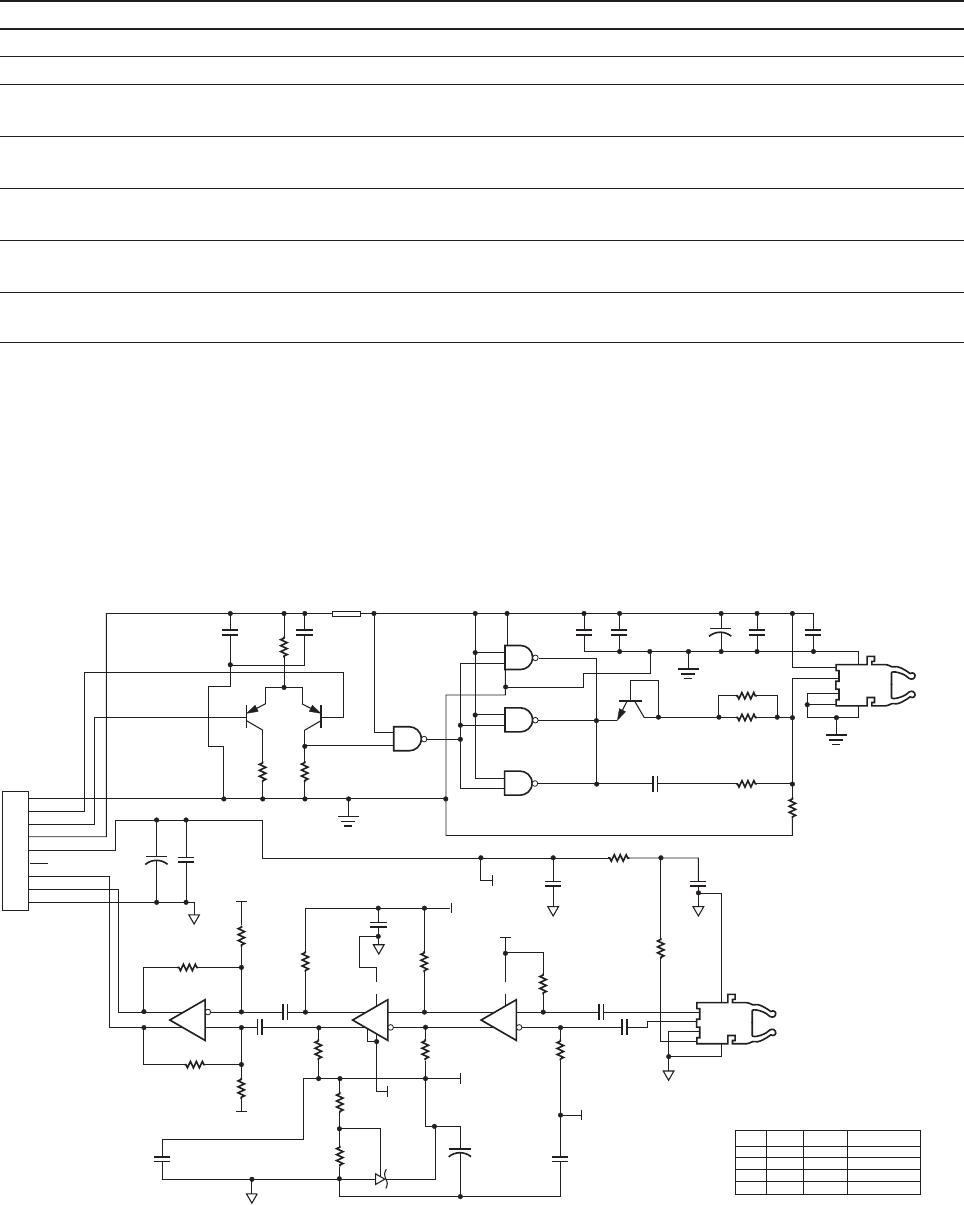
Figure 1. Transmitter and receiver application circuit with +5 V ECL inputs and outputs.
Plastic and Hard Clad Silica Optical Fiber Receiver Application Circuit: Performance
[4]
of the HFBR-25X6Z receiver in the recom-
mended application circuit (Figure 1); 1-125 MBd, 25°C unless otherwise stated.
Parameter Symbol Typical Unit Condition Note
Data Output Voltage - Low V
OL
V
CC
-1.7 V R
L
= 50 Ω Note 5
Data Output Voltage - High V
OH
V
CC
-0.9 V R
L
= 50 Ω Note 5
Receiver Sensitivity to Average P
min
-27.5 dBm 50% eye opening Note 2
Modulated Optical Power 1 mm POF
Receiver Sensitivity to Average P
min
-28.5 dBm 50% eye opening Note 2
Modulated Optical Power 200 μm HCS
Receiver Overdrive Level of Average P
max
-7.5 dBm 50% eye opening Note 2
Modulated Optical Power 1 mm POF
Receiver Overdrive Level of Average P
max
-10.5 dBm 50% eye opening Note 2
Modulated Optical Power 200 μm HCS
Receiver Application Circuit Current I
CC
85 mA R
L
= ∞ Figure 1
Consumption
Notes:
4. Performance in response to a signal from the HFBR-15X7Z transmitter driven with the recommended circuit at 1-125 MBd over 1 meter of
HFBR-RZ/EXXYYYZ plastic optical ber or 1 meter of HFBR-H/VXXYYY hard clad silica optical ber.
5. Terminated through a 50 Ω resistor to V
CC
- 2 V.
6. If there is no input optical power to the receiver, electrical noise can result in false triggering of the receiver. In typical applications, data encod-
ing and error detection prevent random triggering from being interpreted as valid data. Refer to Applications Note 1066 for design guidelines.
C1
0.001
C2
0.1
R5
22
Q1
BFQ52
R6
91
R7
91
Q2
BFQ52
C20
10
C19
0.1
T
X
V
EE
9
8
7
6
5
4
3
2
1
J1
Q2 BASE
Q1 BASE
T
X
V
CC
R
X
V
CC
PIN 19 10H116
PIN 18 10H116
R
X
V
EE
NC
L1
CB70-1812
1
2
3
4
5
13
12
10
9
14
7
8
11
6
1
2
3
4
8
5
8
5
1
2
3
4
12
13
5
7
8
9
3
4
17
15
19
18
R24
1K
R22
1K
R18
51
R16
51
C17
0.1
V
BB
V
CC
C10
0.1
R19
51
R17
51
R15
1K
R23
1K
V
BB
C18
0.1
R25
1K
R20
12
R21
62
V
CC
V
BB
3 V
C14
10
TL431
U5
MC10H116FN
C15
0.1
C11
0.1
C16
0.1
C12
0.1
R14
1K
V
BB
3V
C9
.47
R12
4.7
C13
0.1
HFBR-25X6Z
R13
4.7
U4C U4A U4B U3
R11*
R10
15
C8*
74ACTQ00
U1B
74ACTQ00
U1D
74ACTQ00
U1C
R9*
R8*
HFBR-15X7Z
C7
0.001
C6
0.1
C5
10
C4
0.001
C3
0.1
Q3
2N3904
V
CC
74ACTQ00
U1A
POF
300
300
1K
43 pF
R8
R9
R11
C8
HCS
82
82
470
120 pF
TOLERANCE
1%
1%
1%
1%
THE VALUES OF R8, R9, R11, AND
C8 ARE DIFFERENT FOR POF AND
HCS DRIVE CIRCUITS.
ALL CAPACITOR VALUES
ARE IN MICRO FARADS,
WITH 10% TOLERANCE
(UNLESS OTHERWISE NOTED).
ALL RESISTANCES ARE IN
OHMS WITH 5% TOLERANCE
(UNLESS OTHERWISE NOTED).
U2
MC10H116FN MC10H116FN
2
20
+
+
+
10 14