LTC2941-1
10
29411f
applicaTions inFormaTion
The default value after power up is M = 128 = 2
7
(B[5:3]
= 111). The maximum battery capacity supported within
the prescaler range is 5.5Ah with M = 128. See the section
Extending Coulomb Counter Range if battery capacity is
higher.
Depending on the choice of prescaler factor M, the charge
LSB of the accumulated charge register becomes:
q mAh
M
LSB
= 0 085
128
.
Note that the internal digital resolution of the coulomb
counter is higher than indicated by q
LSB
. The internal
charge resolution is typically 299µAs.
V
BAT
Alert B[7:6]
The V
BAT
alert function allows the LTC2941-1 to monitor
the voltage at SENSE
. If enabled, a drop of the voltage
at the SENSE
pin below a preset threshold is detected
and bit A[1] in the status register is set. If the alert mode
is enabled by setting B[2] to one, an alert is generated at
the AL/CC pin. The threshold for the V
BAT
alert function
is selectable according to Table 3.
Battery voltage is measured at the internal bond pads
connected to SENSE
, hence, the current flowing through
the combined pin and bond wire slightly shifts the battery
alert threshold levels. For the full-scale current of ±1A at
room temperature, this shift is typically ±9mV, which can be
ignored for most applications. The V
BAT
alert thresholds are
specified with zero current through the sense resistor.
Accumulated Charge Register (C,D)
The coulomb counter of the LTC2941-1 integrates current
through its internal sense resistor over time. The result of
this charge integration is stored in the 16-bit accumulated
charge register (registers C, D). The amount of charge for
a given register contents (C[7:0]D[7:0]) and prescaler
setting M can be calculated by:
Q mAh
M
C D= +
( )
0 085
128
256.
The ACR should be read in a single I
2
C Read transaction
(see Figure 8). If C and D are read in individual single-byte
transactions, each with a STOP condition, the register
may change between the first and the second transaction
due to coulomb count events, causing erroneous charge
readings.
As the LTC2941-1 does not know the actual battery status
at power-up, the accumulated charge register (ACR) is set
to mid-scale (7FFFh). If the host knows the status of the
battery, the accumulated charge (C[7:0]D[7:0]) can be
either programmed to the correct value via I
2
C or it can be
set after charging to FFFFh (full) by pulling the AL/CC pin
high if charge complete mode is enabled via bits B[2:1]. In
this case, FFFFh represents a fully charged battery. If the
actual battery capacity is smaller, the host can subtract the
excess charge whenever doing the charge calculation, and
set the low charge threshold (registers G, H) to the value
representing an empty battery. This procedure essentially
shifts the zero point of the scale upwards. Before writing
the accumulated charge registers, the analog section
should be shut down by setting B[0] to 1.
Threshold Registers (E, F), (G, H)
For battery charge, the LTC2941-1 features a high and a
low threshold register. At power-up the high threshold is
set to FFFFh while the low threshold is set to 0000h. Both
thresholds can be programmed to a desired value via I
2
C.
As soon as the accumulated charge exceeds the high
threshold or falls below the low threshold, the LTC2941-1
sets the corresponding flag in the status register and pulls
the AL/CC pin low if alert mode is enabled.
I
2
C Protocol
The LTC2941-1 uses an I
2
C/SMBus compatible 2-wire
open-drain interface supporting multiple devices and
masters on a single bus. The connected devices can only
pull the bus wires low and they never drive the bus high.
The bus wires should be externally connected to a posi-
tive supply voltage via a current source or pull-up resistor.
When the bus is idle, both SDA and SCL are high. Data on
the I
2
C-bus can be transferred at rates of up to 100kbit/s
in standard mode and up to 400kbit/s in fast mode.
Each device on the I
2
C/SMbus is recognized by a unique
address stored in that device and can operate as either a
transmitter or receiver, depending on the function of the
LTC2941-1
11
29411f
device. In addition to transmitters and receivers, devices
can also be classified as masters or slaves when perform-
ing data transfers. A master is the device which initiates a
data transfer on the bus and generates the clock signals
to permit that transfer. At the same time any device ad-
dressed is considered a slave. The LTC2941-1 always
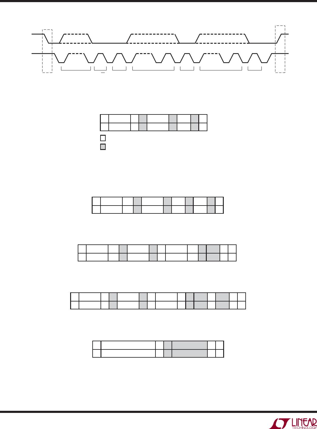
acts as a slave. Figure 4 shows an overview of the data
transmission on the I
2
C bus.
Start and Stop Conditions
When the bus is idle, both SCL and SDA must be high. A
bus master signals the beginning of a transmission with
a START condition by transitioning SDA from high to low
while
SCL
is high. When the master has finished com-
municating with the slave, it issues a STOP condition by
transitioning SDA from low to high while SCL is high. The
bus is then free for another transmission. When the bus is
in use, it stays busy if a repeated START (Sr) is generated
instead of a STOP condition. The repeated START (Sr)
conditions are functionally identical to the START (S).
Data Transmission
After a START condition, the I
2
C bus is considered busy
and data transfer begins between a master and a slave. As
data is transferred over I
2
C in groups of nine bits (eight
data bits followed by an acknowledge bit), each group
takes nine SCL cycles. The transmitter releases the SDA
line during the acknowledge clock pulse and the receiver
issues an acknowledge (ACK) by pulling SDA low or leaves
SDA high to indicate a not-acknowledge (NAK) condition.
Change of data state can only happen while SCL is low.
Write Protocol
The master begins communication with a START condition
followed by the seven bit slave address 1100100 and the
R/W bit set to zero, as shown in Figure 5. The LTC2941-
1 acknowledges this by pulling SDA low and then the
master sends a command byte which indicates which
internal register the master is to write. The LTC2941-1
acknowledges and then latches the command byte into its
internal register address pointer. The master delivers the
data byte, the LTC2941-1 acknowledges once more and
latches the data into the desired register. The transmission
is ended when the master sends a STOP condition. If the
master continues by sending a second data byte instead
of a stop, the LTC2941-1 acknowledges again, increments
its address pointer and latches the second data byte in the
following register, as shown in Figure 6.
Read Protocol
The master begins a read operation with a START condition
followed by the seven bit slave address 1100100 and the
R/W bit set to zero, as shown in Figure 7. The LTC2941-1
acknowledges and then the master sends a command byte
which indicates which internal register the master is to
read. The LTC2941-1 acknowledges and then latches the
command byte into its internal register address pointer. The
master then sends a repeated START condition followed
by the same seven bit address with the R/W bit now set
to one. The LTC2941-1 acknowledges and sends the con-
tents of the requested register. The transmission is ended
when the master sends a STOP condition. If the master
acknowledges the transmitted data byte, the LTC2941-1
increments its address pointer and sends the contents of
the following register as shown in Figure 8.
Alert Response Protocol
In a system where several slaves share a common inter-
rupt line, the master can use the alert response address
(ARA) to determine which device initiated the interrupt
(Figure 9).
The master initiates the ARA procedure with a START con-
dition and the special 7-bit ARA bus address (0001100)
followed by the read bit (R) = 1. If the LTC2941-1 is as-
serting the AL/CC pin in alert mode, it acknowledges and
responds by sending its 7-bit bus address (1100100) and
a 1. While it is sending its address, it monitors the SDA pin
to see if another device is sending an address at the same
time using standard I
2
C bus arbitration. If the LTC2941-1
is sending a 1 and reads a 0 on the SDA pin on the rising
edge of SCL, it assumes another device with a lower ad-
dress is sending and the LTC2941-1 immediately aborts
its transfer and waits for the next ARA cycle to try again.
If transfer is successfully completed, the LTC2941-1 will
stop pulling down the AL/CC pin and will not respond to
further ARA requests until a new alert event occurs.
applicaTions inFormaTion
LTC2941-1
12
29411f
applicaTions inFormaTion
SCL
SDA
START
CONDITION
STOP
CONDITION
ADDRESS R/W ACK DATA ACK DATA ACK
1 - 7 8 9
29411 F04
a6 - a0 b7 - b0 b7 - b0
1 - 7 8 9 1 - 7 8 9
P
S
Figure 4. Data Transfer Over I
2
C or SMBus
FROM MASTER TO SLAVE
S W
ADDRESS REGISTER DATA
FROM SLAVE TO MASTER
29411 F05
A: ACKNOWLEDGE (LOW)
A: NOT-ACKNOWLEDGE (HIGH)
R: READ BIT (HIGH)
W: WRITE BIT (LOW)
S: START CONDITION
P: STOP CONDITION
A A A
0
1100100 01h FCh
0 0 0
P
Figure 5. Writing FCh to LTC2941-1 Control Register (B)
S W
ADDRESS REGISTER DATA
29411 F06
A A A
0
1100100 02h F0h 01h
0 0 0
0
P
DATA
A
Figure 6. Writing F001h to the LTC2941-1 Accumulated Charge Registers (C, D)
S W
ADDRESS REGISTER S
29411 F07
A A ADDRESS
0
1100100 00h 1
0 0 1100100
0
P
R
1
A
81h
DATA
A
Figure 7. Reading the LTC2941-1 Status Register (A)
S W
ADDRESS REGISTER S
29411 F08
A A ADDRESS
0
1100100 02h 1
0 0 1100100
0
P
R
0
A
80h
DATA
01h
DATA
A
1
A
Figure 8. Reading the LTC2941-1 Accumulated Charge Registers (C, D)
S R
ALERT RESPONSE ADDRESS DEVICE ADDRESS
29411 F09
A
1
0001100 11001001
0 1
P
A
Figure 9. LTC2941-1 Serial Bus SDA Alert Response Protocol

LTC2941IDCB-1#TRPBF

Mfr. #:
Manufacturer:
Analog Devices / Linear Technology
Description:
Battery Management 1A I2C Bat Gas Gauge w/ Int Sense Res
Lifecycle:
New from this manufacturer.
Delivery:
DHL FedEx Ups TNT EMS
Payment:
T/T Paypal Visa MoneyGram Western Union