Technical Note
BU7251G,BU7251SG, BU7231G,BU7231SG,
BU7252F/FVM,BU7252S F/FVM,BU7232F/FVM,BU7232S F/FVM
16/18
●Notes for use
1) Absolute maximum ratings
Absolute maximum ratings are the values which indicate the limits, within which the given voltage range can be safely
charged to the terminal.However, it does not guarantee the circuit operation.
2) Applied voltage to the input terminal
For normal circuit operation of voltage comparator, please input voltage for its input terminal within input common mode
voltage VDD+0.3[V].Then, regardless of power supply voltage,VSS-0.3[V] can be applied to inputterminals without
deterioration or destruction of its characteristics.
3) Operating power supply (split power supply/single power supply)
The voltage comparator operates if a given level of voltage is applied between VDD and VSS.
Therefore, the operational amplifier can be operated under single power supply or split power supply.
4) Power dissipation (pd)
If the IC is used under excessive power dissipation. An increase in the chip temperature will cause deterioration of the
radical characteristics of IC. For example, reduction of current capability.
Take consideration of the effective power dissipation and thermal design with a sufficient margin. Pd is reference to the
provided power dissipation curve.
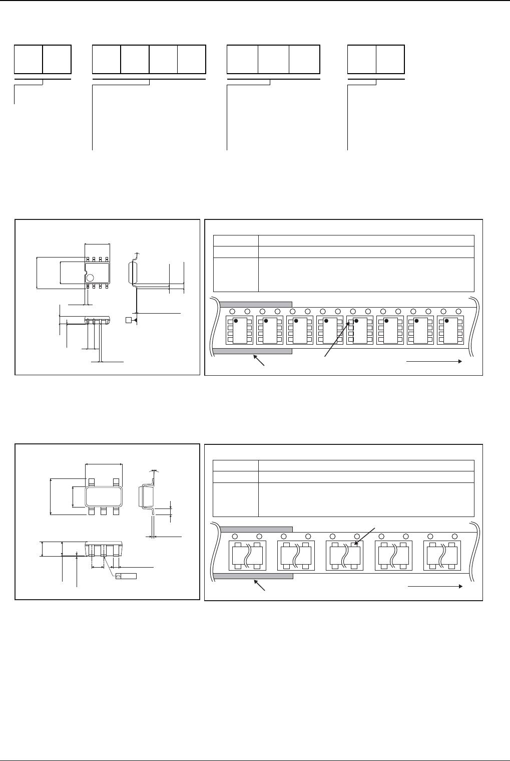
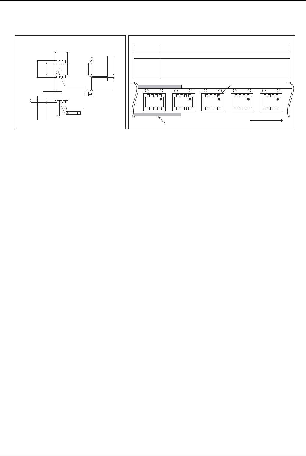
5) Short circuits between pins and incorrect mounting
Short circuits between pins and incorrect mounting when mounting the IC on a printed circuits board, take notice of the
direction and positioning of the IC.
If IC is mounted erroneously, It may be damaged. Also, when a foreign object is inserted between output, between output
and VDD terminal or VSS terminal which causes short circuit, the IC may be damaged.
6) Using under strong electromagnetic field
Be careful when using the IC under strong electromagnetic field because it may malfunction.
7) Usage of IC
When stress is applied to the IC through warp of the printed circuit board,
The characteristics may fluctuate due to the piezo effect. Be careful of the warp of the printed circuit board.
8) Testing IC on the set board
When testing IC on the set board, in cases where the capacitor is connected to the low impedance,make sure to
discharge per fabrication because there is a possibility that IC may be damaged by stress.
When removing IC from the set board, it is essential to cut supply voltage.
As a countermeasure against the static electricity, observe proper grounding during fabrication process and take due
care when carrying and storage it.
9) The IC destruction caused by capacitive load
The transistors in circuits may be damaged when VDD terminal and VSS terminal is shorted with the charged output
terminal capacitor.
When IC is used as a operational amplifier or as an application circuit,where oscillation is not activated by an output
capacitor,the output capacitor must be kept below 0.1[μF] in order to prevent the damage mentioned above.
10) Decupling capacitor
Insert the deculing capacitance between VDD and VSS, for stable operation of operational amplifier.
11) Latch up
Be careful of input vltage that exceed the VDD and VSS. When CMOS device have sometimes occur latch up operation.
And protect the IC from abnormaly noise