LTC4079
12
4079f
For more information www.linear.com/LTC4079
operaTion
IN
INPUT POWER
SOURCE
R
EN1
R
EN2
EN
4079 F05
LTC4079
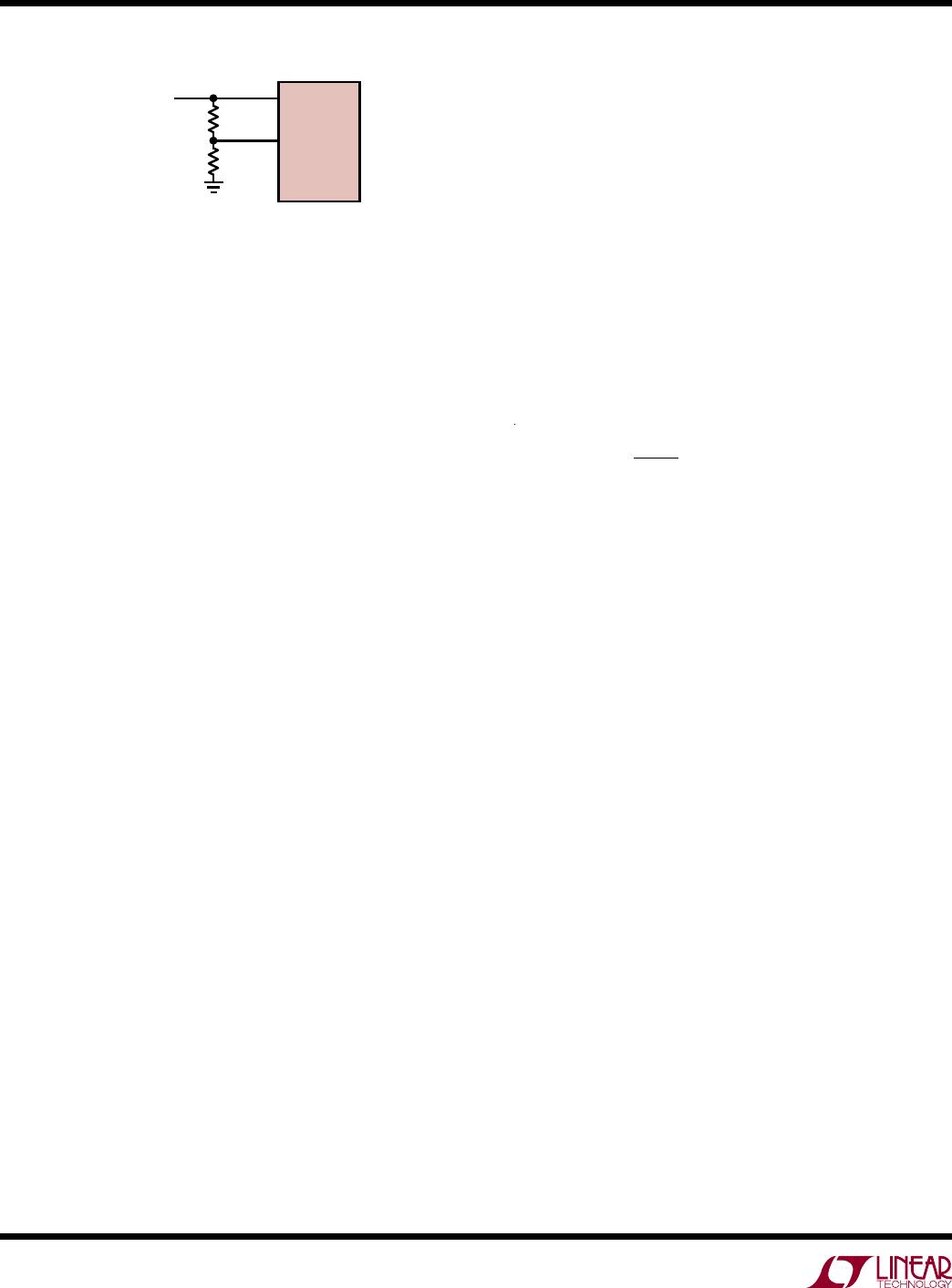
Figure 5. Setting Input Voltage Regulation
Differential Voltage (V
IN
-V
BAT
) Regulation
The LTC4079 provides an additional method to keep the
input voltage from collapsing when the input power comes
from a weak power source. If the input voltage falls close
to the battery voltage, the differential voltage regulation
loop in LTC4079 keeps the input voltage above the battery
voltage by 160mV (typical value) by reducing the charge
current as the input to battery differential voltage falls.
In both of the above regulation conditions, the input source
must provide at least the quiescent current of the device to
prevent UVLO. The charge timer is paused whenever the
charge current is reduced due to input voltage regulation
or differential voltage regulation.
Thermal Regulation
An internal thermal feedback loop reduces the charge
current below the programmed value if the die temperature
approaches 118°C. This feature protects the LTC4079
from excessive temperature and allows the user to set
the charge current to typical (not worst case) ambient
temperature with the assurance that the charger will
automatically reduce the current to prevent overheating
in worst-case conditions.
The charge timer is paused during thermal limiting to
prevent under-charging the battery and to allow the
full
charge current to flow for the set timer duration.
C/10 T
ermination
The LTC4079 supports a current based termination scheme,
where a battery charge cycle terminates when the current
output from the charger falls below one-tenth of the
programmed charge current. The C/10 threshold current
corresponds to 119mV on the PROG pin. This termination
mode is engaged by shorting the TIMER pin to ground.
When C/10 termination is used, the LTC4079 provides
battery charge current as long as the current remains
above the C/10 threshold. As the battery terminal voltage
reaches the target charge voltage, the charge current falls
until the C/10 threshold is reached, at which time the
charger terminates and the LTC4079 enters standby mode.
Premature termination is prevented when input voltage,
differential or thermal regulation is active.
To prevent termination-recharge oscillations, it is important
to set the termination charge current low enough for bat
-
teries with
high internal resistance. For a nominal recharge
threshold
of 2.4% below the charge voltage, the charge
current should be set as follows with sufficient margin:
I
CHG
< 0.24 •
V
CHG
R
BAT
where R
BAT
is the battery's internal series resistance. The
CHRG status pin is high impedance when the charger is
not actively charging.
Timer Termination
The LTC4079 also supports a timer-based termination
scheme, where the battery charge cycle is terminated after
a specific amount of time elapses. Connect a capacitor
from the TIMER pin to ground to engage timer based
charge termination. Calculate the capacitance required
for the desired charge cycle duration, t
TIMER
as follows:
C
TIMER
= t
TIMER
• 18.2nF/Hr
A 200nA current source is used to source/sink current
to/from C
TIMER
to generate a sawtooth periodic signal
(nominally 0.8V to 1.2V) for use by the timer. Since the
TIMER pin current is small, minimize leakage on this pin
to maintain timer accuracy.
The timer starts on charger enable or the beginning of a
recharge cycle, and is reset on disable or when V
IN
falls
below UVLO or DUVLO.
The timer is paused whenever the charge current is limited
by EN pin or differential voltage or thermal regulation,
unless the charger is also in constant-voltage regulation
mode. It is also paused with the charge current during an
NTC fault. The timer
is not paused if the charge current is