LTC4079
13
4079f
For more information www.linear.com/LTC4079
operaTion
limited by dropout. For example, for a programmed charge
current of 100mA, this occurs when V
IN
-V
BAT
falls below
about 0.5V due to the voltage drop across the charge path
(5Ω typically). If V
IN
-V
BAT
falls below 160mV to trigger
differential voltage regulation, the timer will be paused.
The CHRG status pin signals charging at a rate of more
than C/10, regardless of which termination scheme is
used. When timer termination is used, the CHRG status
pin pulls low during a charging cycle until the charger
output current falls below the C/10 threshold. The charger
continues to top off the battery until timer termination,
when the LTC4079 enters standby mode.
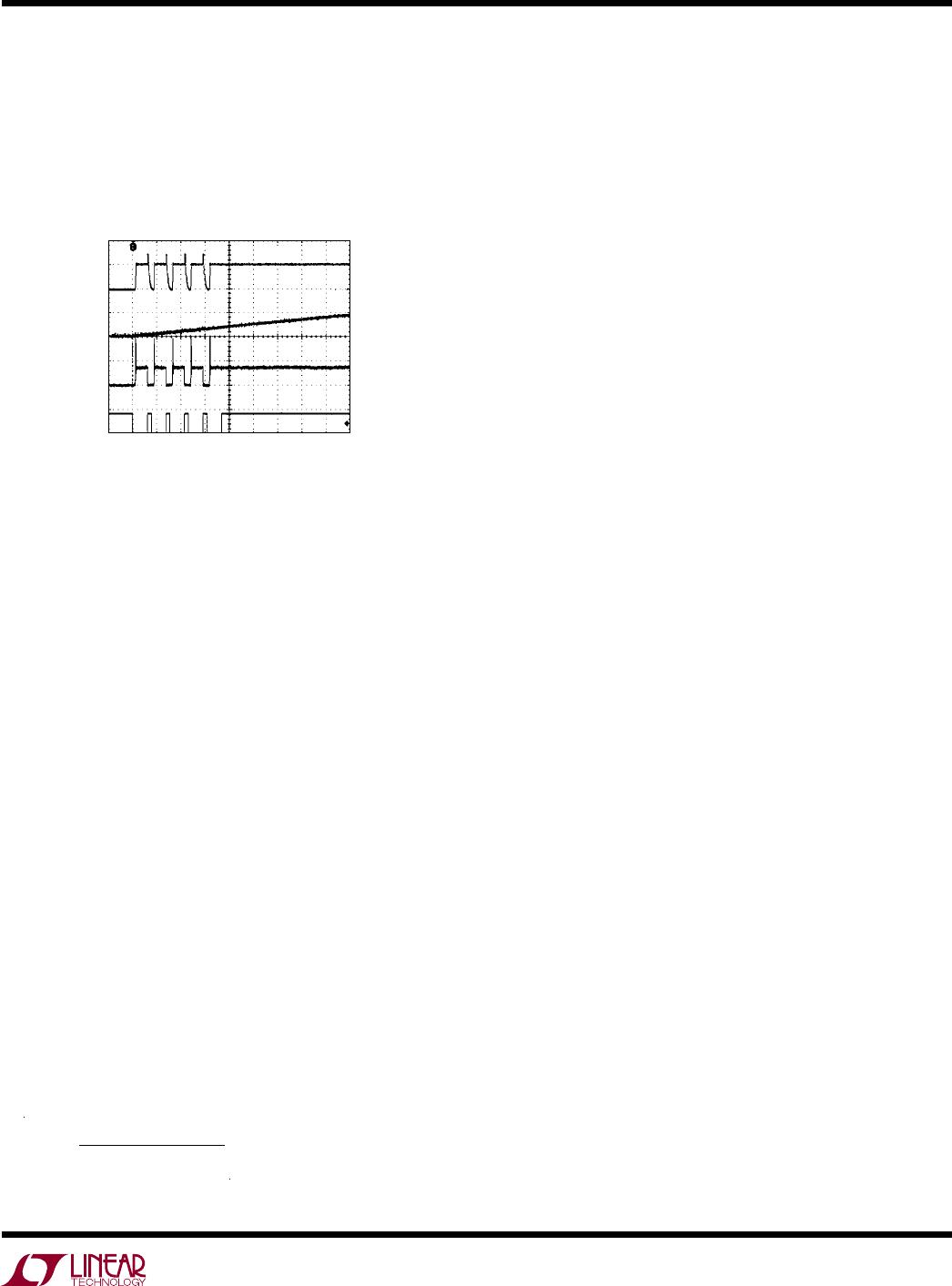
Standby and Automatic Recharge
If the LTC4079 remains enabled after charge cycle
termination, it monitors the battery voltage in standby
mode by sampling the FB pin connected to the external
resistor divider. In order to minimize the battery drain, the
feedback divider is only turned on (by connecting FBG pin
to ground) for 210µs once every 3 seconds. When this
sampling detects that the battery voltage has dropped
by more than 2.4%, the feedback divider is kept on for
1.5 seconds (typical). If the FB voltage remains below
the recharge
threshold for
more than 2.5ms (typical), a
recharge cycle starts. This 2.5ms filter prevents premature
recharge due to load transients. The recharge cycle also
terminates in constant-voltage charge mode as described
above. The automatic recharge function maintains that the
battery at, or near, a fully charged condition.
If the battery voltage remains below the recharge threshold
on timer expiration, another recharge cycle begins as
explained below.
Timer Retry and Latch-off
A new charge cycle is started if the battery voltage remains
below the recharge threshold at the end of a charge cycle.
This happens in the following situations: 1) the timer is
not set long enough for the battery with the programmed
charge current, 2) the battery is defective, 3) a load drains
the battery during charging, 4) charge current is limited
by dropout.
In order to avoid wasting power in recharging a defective
battery indefinitely, LTC4079 contains a recharge latch-
off feature. Charging is latched off and the CHRG pin
remains asserted after 5 recharge attempts if the battery
voltage remains below the recharge threshold at the end
of all five recharge cycles. The latch-off counter is reset
if a charge cycle terminates normally during any recharge
attempt, or if the
charge current falls below I
CHG
/10 in
constant-voltage regulation mode during a charge cycle.
Charger disable using the EN pin or UVLO also resets the
latch-off counter..
Bad Battery Scenario
If the feedback voltage remains below V
FB(LOWBAT)
for
longer than 1/4th of the safety timer set by C
TIMER
, the
battery is considered bad. Charging stops in this case and
the CHRG pin remains asserted. NTC sampling and FB
sampling for recharge is also turned-off. The charge cycle
is restarted by toggling the EN pin below V
EN(SD)
(typically
0.75V) and then back high. UVLO also clears the bad battery
lockout. There is no bad battery detection when the battery
charge timer is disabled (TIMER pin grounded).
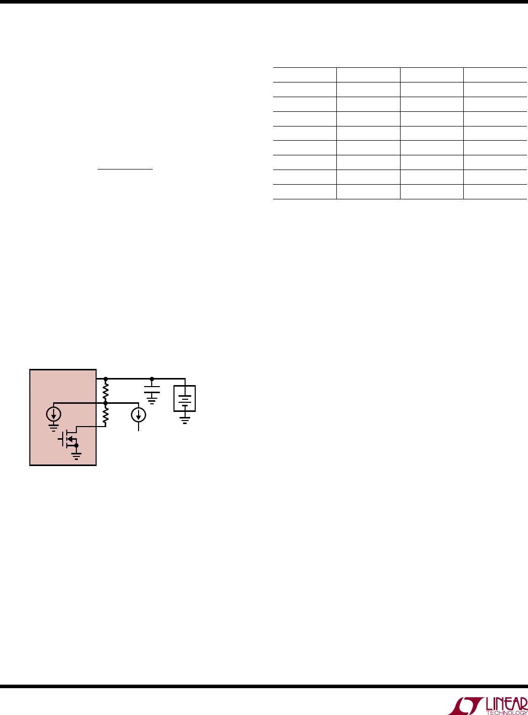
CHRG Status Output
The charge status open-drain output (CHRG) has two
states: pull down and high impedance. The pull-down
state indicates that LTC4079 is in charging mode. A high
impedance state indicates that the charge current has
dropped below 10% of the programmed charge current. In
most cases, charge current is reduced due to the constant-
voltage loop, meaning that the battery voltage is near the
target charge voltage. But if charge current is reduced due
to
V
IN
regulation (through EN or V
IN
-V
BAT
regulation) or
thermal regulation, CHRG remains asserted until only the
constant-voltage regulation loop reduces charge current
below 10% of the programmed charge current.
A high impedance state at the CHRG pin occurs on timer
termination, or UVLO or differential UVLO, or when the
LTC4079 is disabled by pulling EN low. This output can
be used as a logic interface or to light a low power LED.
LTC4079
14
4079f
For more information www.linear.com/LTC4079
applicaTions inForMaTion
Feedback Divider Selection
Using too low or too high values of resistors for the
feedback divider can cause small charge voltage errors
due to: 1) Finite on-resistance of the internal switch on
the FBG pin and 2) leakage on the FB pin. The impact of
these two factors on the target battery charge voltage is
calculated as follows:
V
CHG
= 1.170V 1+
R
FB1
R
FB2
+R
FBG
+R
FB1
(I
FB
+I
LEAK
)
where R
FB1
and R
FB2
are the top and bottom resistors of
the feedback divider, R
FBG
is the resistance of the internal
switch from the FBG pin to GND (160Ω typical) and I
LEAK
is the parasitic leakage on the FB pin as shown in Figure
6. A graph of I
FB
vs Temperature is given in the Typical
Performance section.
According to the above equation, high value feedback
resistors minimize the impact of R
FBG
, while low values
minimize the impact of I
FB
and l
LEAK
. A Thevenin equivalent
resistance of 100k to 500k on the FB node is generally a
good compromise in most scenarios.
Table 1. Recommended 1% Resistors for Common Battery
Charge Voltages
V
CHG
R
FB1
R
FB2
TYPICAL ERROR
3.6V 1070k 511k +0.53%
4.1V 422k 169k –0.27%
4.2V 1070k 412k +0.18%
7.2V 1370k 267k –0.42%
8.2V 1070k 178k -0.04%
8.4V 1540k 249k +0.02%
12.3V 1780k 187k -0.02%
12.6V 2550k 261k -0.05%
Stability Considerations
When the charger is in constant-current mode, the PROG
pin impedance forms part of the charger current control
loop. The constant-current mode stability is therefore
affected by the roll-off frequency of the PROG pin
impedance. With minimum capacitance on this pin (less
than about 10pF), the charger is stable with a program
resistor, R
PROG
, as high as 60k (I
CHG
= 5mA); however,
any additional capacitance at this pin limits the maximum
allowed program resistor.
The constant-voltage loop is stable without any
compensation as long as a typical low impedance battery
is connected to the BAT pin. However, aF capacitor with
series resistor is recommended when charging high
ESR batteries, typically more than 1kΩ.
Charging High Resistance Batteries
When charging a battery with high internal resistance,
the battery voltage can rise quickly, entering constant-
voltage mode. If the charge current falls below 1/10th of
the programmed charge current, charging may terminate
based on
C/10 even if a timer capacitor is connected
on
the TIMER pin. This is because C/10 termination is
assumed if the timer pin remains below 0.3V. With only
200nA being sourced from the TIMER pin, a large timer
capacitance may limit the TIMER voltage below 0.3V for
a short duration at the beginning of a charge cycle. After
charging terminates, a recharge cycle would begin if the
+
BAT
FB
LTC4079
PARASITIC
LOAD
R
FB1
R
FB2
I
LEAK
4079 F06
BATTERY
FBG
ENABLE
I
FB
Figure 6. Feedback Divider Considerations
For example, for R
FB1
= 1.54M and R
FB2
= 249k (for bat-
tery charge voltage of 8.4V), accounting for R
FBG
=160Ω
lowers the charge voltage by 0.06%, while I
LEAK
= 10nA
raises it by 0.18%.
Table 1 lists possible choices of standard 1% resistor
values for common battery charge voltages. The Typical
Error column gives systematic error due to the granularity
in the values of 1% resistors.
LTC4079
15
4079f
For more information www.linear.com/LTC4079
applicaTions inForMaTion
internal battery voltage has not been charged above the
recharge threshold, determined by V
RECHRG
and the
feedback divider. As shown in Figure 7, this charge/recharge
cycle continues until the TIMER pin rises above 0.3V, at
which point timer termination is engaged and the battery
is charged for the duration set by the timer capacitor.
Example: Consider an LTC4079 operating from a 12V
input source programmed to supply 100mA current to
a discharged 2-cell Li-Ion battery with a voltage of 6.6V.
Assuming θ
JA
is 43°C/W the ambient temperature at which
the charge current begins to fall due to thermal regulation is:
T
A
= 118°C – (12V-6.6V) • 100mA • 43°C/W = 95°C
The LTC4079 can be used above 95°C ambient but the
charge current will be reduce linearly from the programmed
value of 100mA to 0mA as the ambient temperature
increases from 95°C to 118°C.
Increasing Thermal Regulation Current
In applications with large V
IN
to V
BAT
drop, the charge
current can be significantly reduced during thermal regula-
tion. One
way to increase the thermally regulated charge
current
is to dissipate some of the power in a resistor in
series with the IN pin. This works well when
the resistor
value
is designed to be small enough to avoid pushing the
LTC4079 into dropout.
Input Capacitor Selection
When an input supply is connected to a portable product,
the inductance of the cable and the high Q ceramic input
capacitor form an L-C resonant circuit. While the LTC4079
is capable of withstanding input voltages as high as 62V, if
the input cable does not have adequate mutual inductance
or if there is not much impedance in the cable, it is possible
for the voltage at the input of LTC4079 to reach as high as
2x the cable input voltage before it settles out. To prevent
excessive voltage from damaging the LTC4079 during a
hot insertion, it is best to have a low voltage coefficient
capacitor at the supply input pin of the LTC4079.
Using a tantalum capacitor or an aluminum electrolytic
capacitor for input bypassing, or paralleling with a ce
-
ramic capacitor
will
also reduce voltage overshoot during
a hot insertion.
Power Dissipation and Thermal Regulation
The LTC4079 automatically reduces charge current
during high power conditions that result in high junction
temperature. Therefore, it is not necessary to design
the charging system for worst-case
power dissipation
scenarios. The conditions that cause the LTC4079 to
reduce charge current through thermal regulation can be
approximated by considering the power dissipated in the
IC. Most of the power dissipation is in the charge path.
Thus the power dissipation is approximately:
P
D
= (V
IN
-V
BAT
) • I
BAT
The approximate ambient temperature at which the thermal
regulation begins to lower the charge current is:
T
A
= 118°C – P
D
θ
JA
T
A
= 118°C – (V
IN
-V
BAT
) • I
BAT
θ
JA
The reduced charge current at an ambient temperature
above the onset of thermal regulation can be calculated
as follows:
I
BAT
=
118°C T
A
V
IN
V
BAT
( )
θ
JA
Figure 7. Repeated Charge Terminations on
Startup Due to High Resistance of the Battery,
C
TIMER
=82nF, V
CHG
=4.2V, I
CHG
=10mA and
Battery Resistance=300Ω
V
BAT
0.2V/DIV
TIMER
0.5V/DIV
PROG
0.1V/DIV
CHRG
5V/DIV
20ms/DIV
4079 F01
4.2V

LTC4079EDD#PBF

Mfr. #:
Manufacturer:
Analog Devices / Linear Technology
Description:
Battery Management Low Iq 60V, 250mA Linear Charger
Lifecycle:
New from this manufacturer.
Delivery:
DHL FedEx Ups TNT EMS
Payment:
T/T Paypal Visa MoneyGram Western Union