LTC4079
17
4079f
For more information www.linear.com/LTC4079
Typical applicaTions
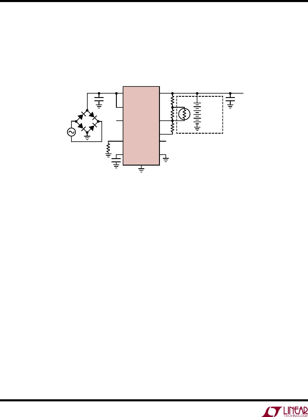
Li-Ion Charger with Timer Termination
In the Figure 8 configuration, the input source charges
the battery for 5½ hours and also supplies current to the
load. The maximum current provided by the charger (on
BAT pin) is limited to the charge current of 246mA set by
the 1.21k resistor on the PROG pin. A small resistor is
used in series with the input supply to reduce V
IN
-V
BAT
,
and thereby increase the available charge current during
thermal regulation. Once the battery is charged, it sup
-
plies power to the load until V
BAT
falls below the recharge
threshold, at which point a recharge cycle starts.
Figure 8. Li-Ion Charger with Timer Termination
BAT
FB
FBG
EN
NTCBIASPROG
NTC
GND
LTC4079
TIMER
1.54M
1.21k
25Ω, 2W
100nF
1µF
TO
LOAD
249k
10k
4079 F08
BATTERY
PACK
V
CHG
= 8.4V
I
CHG
= 246mA
CHRG
IN
24V
SUPPLY
+
T
10k
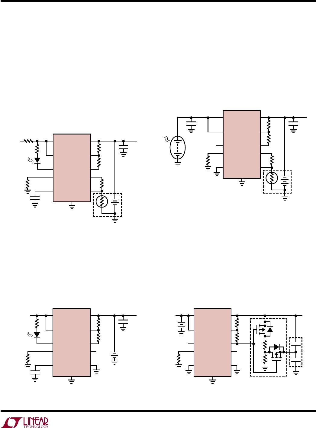
2-Cell NiMH Trickle Charger from Automotive Supply
with Timer Termination
Figure 9 shows a trickle charger for 2-cell, 2500mAh,
AA NiMH battery with timer termination after 31 hours.
Charge current drops when the battery voltage reaches
1.65V per cell.
Figure 9. NiMH Trickle Charger with Timer Termination
BAT
FB
FBG
EN
NTCBIASPROG
NTC
GND
LTC4079
TIMER
324k
3.01k
560nF
1µF
TO
LOAD
178k
4079 F09
2500mAh
2-CELL
NiMH
V
CHG
= 3.3V
I
CHG
= 99mA
CHRG
IN
12V
CAR BATTERY
+
Li-Ion Charging from a Solar Panel with Differential
Voltage Regulation, C/10 Termination
Figure 10 shows a simple charging solution from a solar
panel. Differential voltage regulation reduces charge current
to prevent the panel voltage from drooping below the
battery voltage when charging under low light conditions.
The LTC4079 does not require a Schottky diode in series
with the panel.
Supercapacitor Charger from 2-Cell Li-ion
Charging terminates when the stacked supercapacitor
voltage reaches the set charge voltage. A recharge cycle
begins automatically when the supercap voltage falls
below the recharge threshold. A resistor divider balancer
can optionally be switched in for balancing a stacked
supercapacitor during charging.
Figure 10. Li-Ion Charger with Differential Voltage Regulation
BAT
FB
FBG
EN
NTCBIASPROG
NTC
GND
LTC4079
TIMER
1.54M
1.21k
1µF1µF
TO
LOAD
249k
10k
4079 F10
BATTERY
PACK
V
CHG
= 8.4V
I
CHG
= 246mA
CHRG
IN
+
SOLAR
PANEL
+
–
T
10k
Figure 11. Supercap Charger with C/10 Termination
BAT
2-CELL
Li-Ion
FB
FBG
EN
NTCBIASPROG
NTC
GND
LTC4079
TIMER
1.02M
30.1k
C
SC
0.6F
HS206
TO
LOAD
309k
1k
1k
SUPERCAP BALANCER (OPTIONAL)
FDG6308P
4079 F11
V
CHG
= 5.0V
I
CHG
= 10mA
CHRG
IN
+