22
LTC1197/LTC1197L
LTC1199/LTC1199L
Data Exchange Between LTC1199 and MC68HC05C4
Hardware and Software Interface to Motorola MC68HC05C4
LABEL MNEMONIC COMMENTS
START BCLRn Bit 0 Port C goes low (CS goes low)
LDA Load LTC1199 D
IN
word into ACC
STA Load LTC1199 D
IN
word into SPI from ACC
Transfer begins
TST Test status of SPIF
BPL Loop to previous instruction if not done
with transfer
LDA Load contents of SPI data register
into ACC (D
OUT
MSBs)
STA Start next SPI cycle
AND Clear 6 MSBs of the first D
OUT
word
STA Store in memory location A (MSBs)
TST Test status of SPIF
BPL Loop to previous instruction if not done
with transfer
BSETn Set B0 of Port C (CS goes high)
LDA Load contents of SPI data register into
ACC. (D
OUT
LSBs)
STA Store in memory location A + 1 (LSBs)
MPU TRANSMIT
WORD
CS
CLK
D
OUT
MPU RECEIVED
WORD
D
IN
1
ODD/
SIGN
XXXX
SGL/
DIFF
XXXXXXXX
START
BIT
BYTE 1 BYTE 2 (DUMMY)
X = DON‘T CARE
START DUMMY
SGL/
DIFF
DON‘T CARE
B9 B8 B7 B6 B5 B4 B3 B2 B1 B0
ODD/
SIGN
DUMMY
????00B9B8
B7 B6 B5 B4 B3 B2 B1 B0
2ND TRANSFER1ST TRANSFER
1197/99 TA03
D
OUT
from LTC1199 Stored in MC68HC05C4
LOCATION A + 1
LSB
MSB
LOCATION A
BYTE 2
BYTE 1
1197/99 TA05
B7 B6 B5 B4 B3 B2 B1 B0
000000B9B8
TYPICAL APPLICATIO S
U
1197/99 TA04
CLK
D
IN
CS
ANALOG
INPUTS
C0
SCK
D
OUT
MISO
MOSI
MC68HC05C4
LTC1199
23
LTC1197/LTC1197L
LTC1199/LTC1199L
Interfacing to the Parallel Port of the
Intel 8051 Family
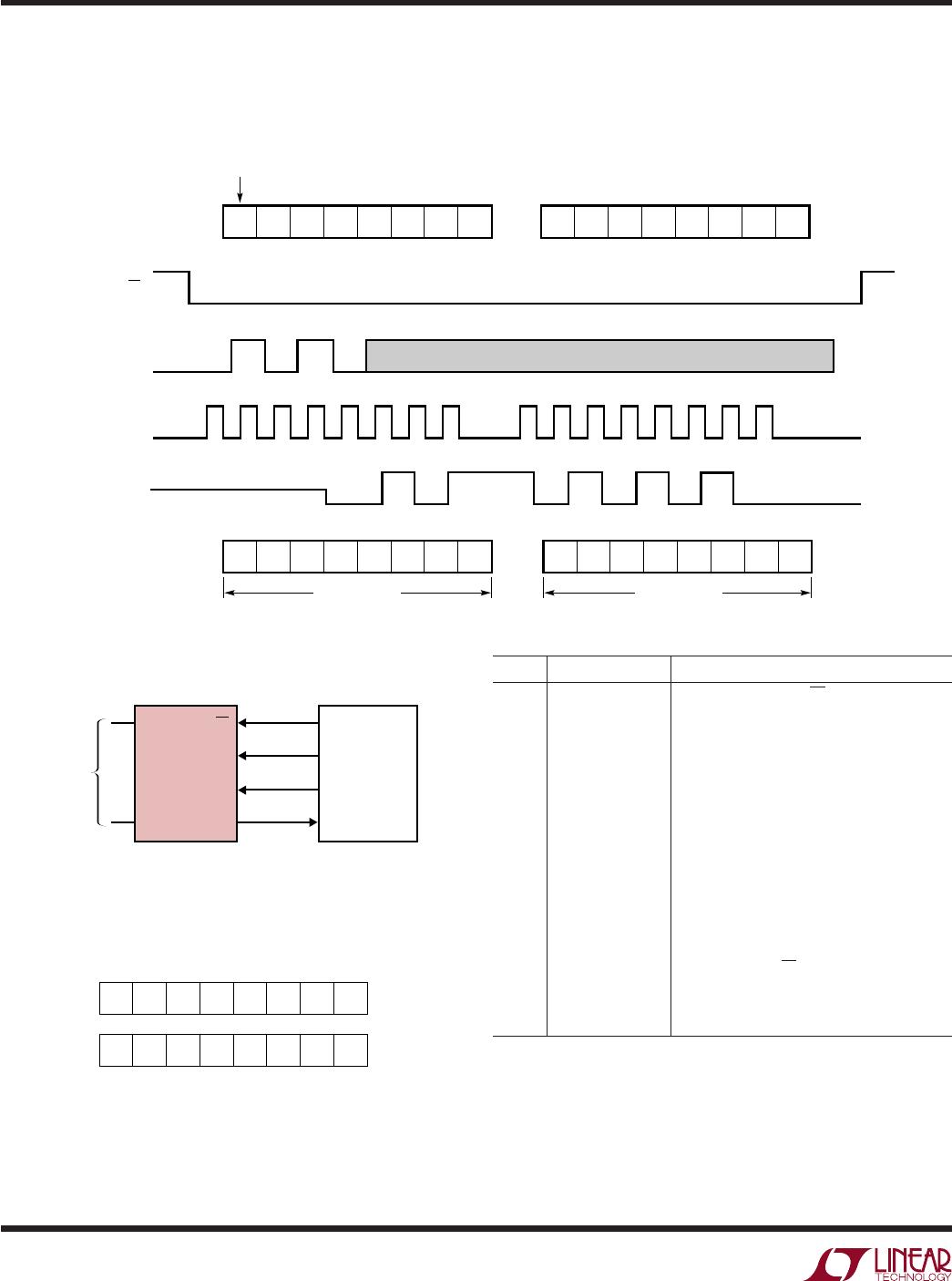
The Intel 8051 has been chosen to demonstrate the
interface between the LTC1199 and parallel port micro-
processors. Normally, the CS, CLK and D
IN
signals would
be generated on three port lines and the D
OUT
signal read
on a fourth port line. This works very well. However, we
will demonstrate here an interface with the D
IN
and D
OUT
of the LTC1199 tied together as described in the
SERIAL INTERFACE section. This saves one wire.
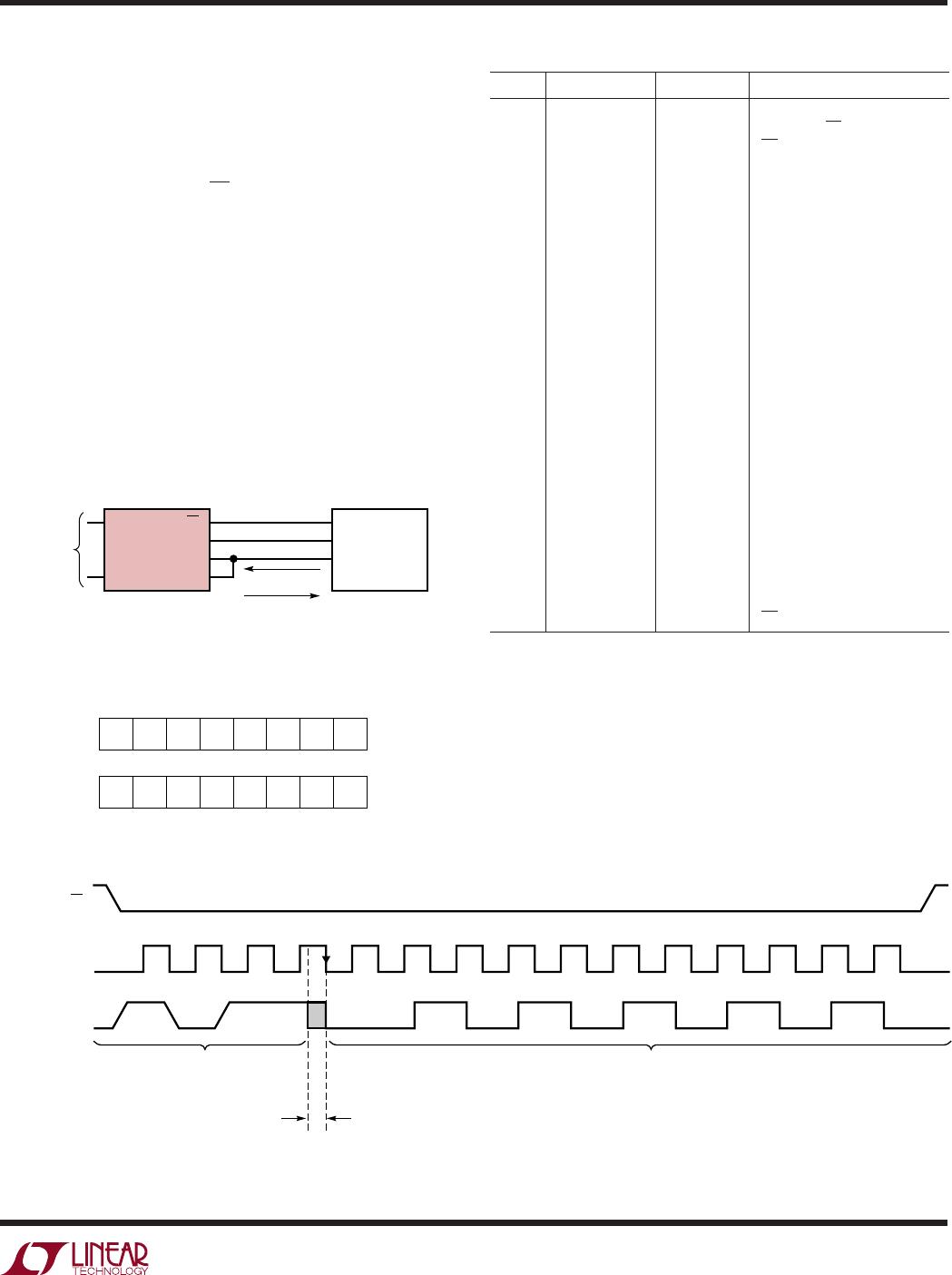
The 8051 first sends the start bit and MUX address to the
LTC1199 over the data line connected to P1.2. Then P1.2
is reconfigured as an input (by writing to it a one) and
the 8051 reads back the 8-bit A/D result over the same
data line.
LABEL MNEMONIC OPERAND COMMENTS
MOV A, #FFH D
IN
word for LTC1199
SETB P1.4 Make sure CS is high
CLR P1.4 CS goes low
MOV R4, #04 Load counter
LOOP 1 RLC A Rotate D
IN
bit into Carry
CLR P1.3 CLK goes low
MOV P1.2, C Output D
IN
bit into Carry
SETB P1.3 CLK goes high
DJNZ R4, LOOP 1 Next bit
MOV P1, #04 Bit 2 becomes an input
CLR P1.3 CLK goes low
MOV R4, #0AH Load counter
LOOP MOV C, P1.2 Read data bit into Carry
RLC A Rotate data bit into ACC
SETB P1.3 CLK goes high
CLR P1.3 CLK goes low
DJNZ R4, LOOP Next bit
MOV R2, A Store MSBs in R2
MOV C, P1.2 Read data bit into Carry
SETB P1.3 CLK goes high
CLR P1.3 CLK goes low
CLR A Clear ACC
RLC A Rotate data bit from Carry to
ACC
MOV C, P1.2 Read data bit into Carry
RRC A Rotate right into ACC
MOV R3, A Store LSBs in R3
SETB P1.4 CS goes high
D
OUT
from LTC1199 Stored in 8051 RAM
1
CS
CLK
DATA (D
IN
/D
OUT
)
START
ODD/
SIGN
DUMMY
B9
LTC1199 SENDS A/D RESULT
BACK TO 8051 P1.2
8051 P1.2 OUTPUTS DATA
TO LTC1199
8051 P1.2 RECONFIGURED
AS AN INPUT AFTER THE 4TH RISING
CLK AND BEFORE THE 4TH FALLING CLK
LTC1199 TAKES CONTROL OF DATA LINE
ON 4TH FALLING CLK
234
SGL/
DIFF
B8 B7 B6 B5 B4 B3 B2 B1 B0
1197/99 TA08
R2
1197/99 TA07
MSB
B9 B8 B7 B6 B5 B4 B3 B2
R3
LSB
B1 B0 0 0 0 0 0 0
TYPICAL APPLICATIO S
U
CS
CLK
D
OUT
D
IN
LTC1199
ANALOG
INPUTS
P1.4
P1.3
P1.2
8051
MUX ADDRESS
A/D RESULT
1197/99 TA06
24
LTC1197/LTC1197L
LTC1199/LTC1199L
A “Quick Look” Circuit for the LTC1197
Users can get a quick look at the function and timing of
the LTC1197 by using the following simple circuit (Figure
11). V
REF
is tied to V
CC
. V
IN
is applied to the +IN input and
the –IN input is tied to the ground. CS is driven at 1/16
the clock rate by the 74HC161 and D
OUT
outputs the data.
The output data from the D
OUT
pin can be viewed on an
oscilloscope that is set up to trigger on the falling edge
of CS (Figure 12). Note that after the LSB is clocked out,
the LTC1197 clocks out zeros until CS goes high. Also
note that with the resistor divider on D
OUT
the output
goes midway between V
CC
and ground when in the high
impedance mode.
Figure 11. “Quick Look” Circuit for the LTC1197
CLK
CS
D
OUT
FILL
ZEROES
HIGH
IMPEDANCE
2 NULL
BITS
MSB
(B9)
LSB
(B0)
VERTICAL: 5V/DIV
HORIZONTAL: 10µs/DIV
Figure 12. Scope Photo of the LTC1197 “Quick Look” Circuit
Waveforms Showing A/D Output 1001001001 (249
HEX
)
TYPICAL APPLICATIO S
U
CLR
CLK
A
B
C
D
P
GND
V
CC
RC
QA
QB
QC
QD
T
LOAD
74HC161
V
IN
TO OSCILLOSCOPE
D
OUT
CLK CS
1197/99 F11
V
CC
CLK
D
OUT
V
REF
LTC1197
CS
+IN
–IN
GND
1µF
5V
10k
CLK IN 7.2MHz MAX
10k
5V
+

LTC1197LCMS8#TRPBF

Mfr. #:
Manufacturer:
Analog Devices Inc.
Description:
Analog to Digital Converters - ADC 250ksps Diff input 3V 10-Bit ADC
Lifecycle:
New from this manufacturer.
Delivery:
DHL FedEx Ups TNT EMS
Payment:
T/T Paypal Visa MoneyGram Western Union