HMC7992 Data Sheet
Rev. 0 | Page 12 of 13
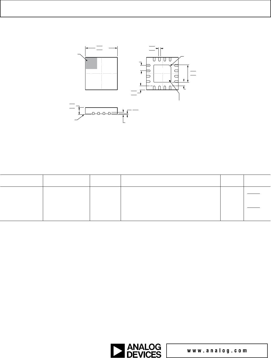
APPLICATIONS INFORMATION
Generate the evaluation PCB with proper RF circuit design
techniques. Signal lines at the RF port must have a 50 Ω
impedance, and the package ground leads and backside ground
slug must connect directly to the ground plane, as shown in
Figure 23. The evaluation board shown in Figure 23 is available
from Analog Devices, Inc., upon request.
Table 8. Bill of Materials for the EV1HMC7992LP3D
1
Evaluation Board
Reference Designator Description
J1 to J5 PCB mount SMA connectors
C1 to C5 100 pF capacitors, 0402 package
C8 to C10 100 pF capacitors, 0402 package
C13 0.1 μF capacitor, 0402 package
R1 to R2 0 Ω resistors, 0402 package
U1 HMC7992LP3DE SP4T switch
PCB
2
600-01284-00 evaluation PCB
1
Reference this evaluation board number when ordering the complete
evaluation board.
2
Circuit board material: Roger 4350 or Arlon 25FR.
13714-017
Figure 23. E
V1HMC7992LP3D Evaluation Board