TQ
–10–
ASCTB14E 201407-T
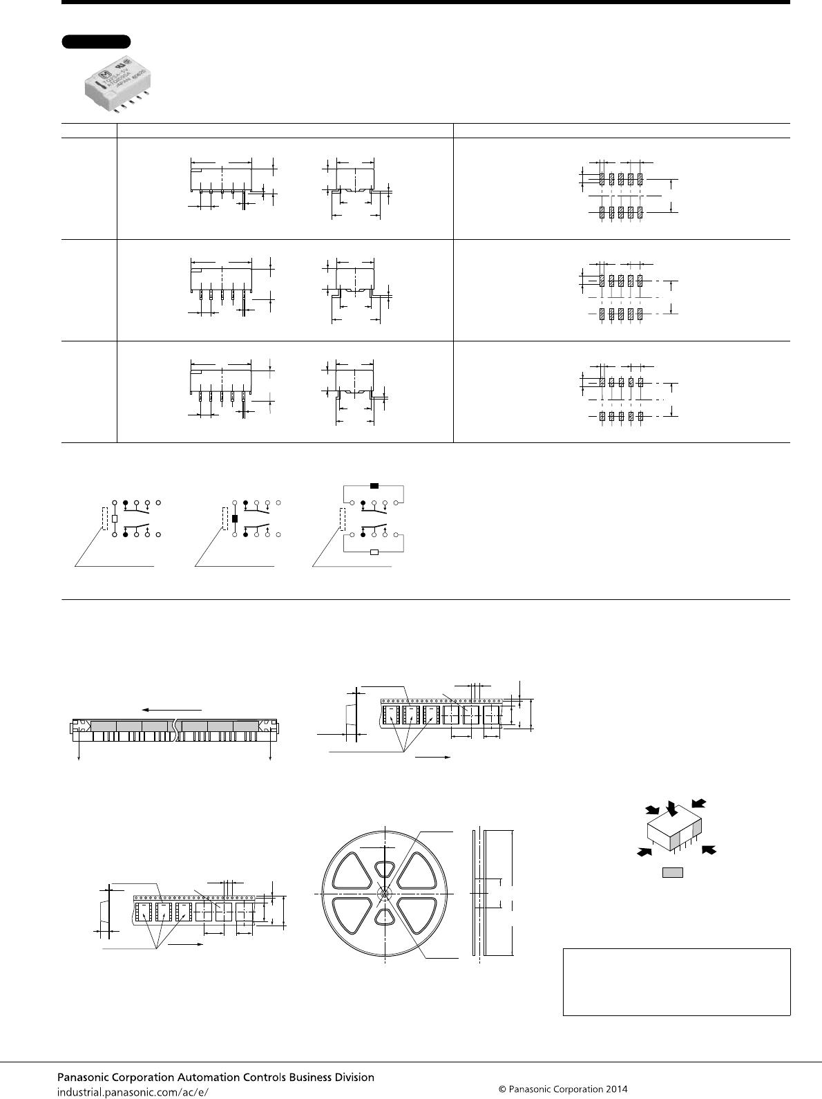
DIMENSIONS (mm inch)
1. Standard PC board terminal and Self-clinching terminal
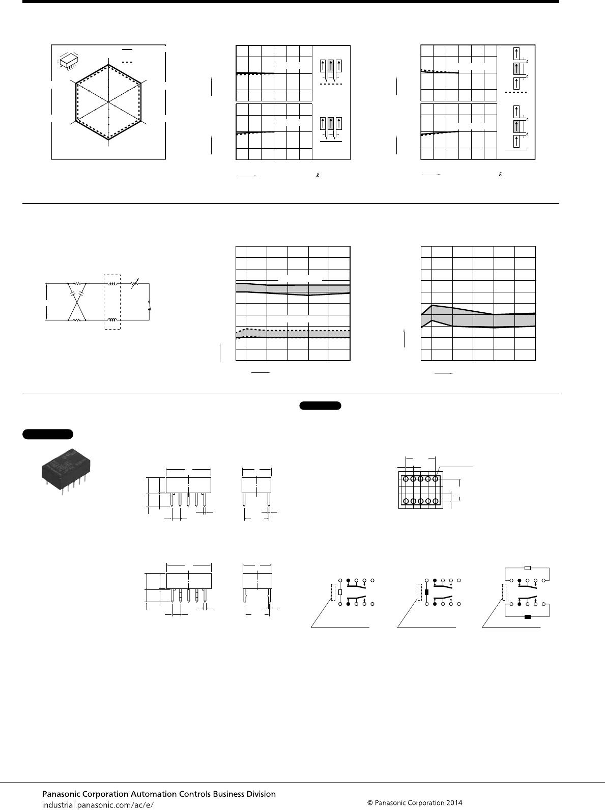
9. Malfunctional shock (single side stable)
Tested sample: TQ2SA-12V, 6 pcs
10.-(1) Influence of adjacent mounting
Tested sample: TQ2SA-12V, 5 pcs.
10.-(2) Influence of adjacent mounting
Tested sample: TQ2SA-12V, 6 pcs.
Y'
Y
XZ'
ZX'
Y
Y'
Z'
Z
X
X'
1000m/s
2
2
2
1000m/s
2
1000m/s
1000m/s
1000m/s
1000m/s
Deenergized
condition
Energized
condition
2
2
–10
0
10
–10
0
10
ON ON
ON
OFF OFF
OFF
5312 406
Inter-relay distance , mm inch
Pick-up voltage
Drop-out voltage
Rate of change, % Rate of change, %
.197.118.039 .079 .157 .236
–10
0
10
–10
0
10
ON
ON
ON
OFF
OFF
OFF
0
5312 4 6
Inter-relay distance , mm inch
Pick-up voltage
Drop-out voltage
Rate of change, % Rate of change, %
.197.118.039 .079 .157 .236
11. Pulse dialing test
(35 mA 48 V DC wire spring relay load)
Tested sample: TQ2SA-12V, 6 pcs.
Circuit
Change of pick-up and drop-out voltage
(mounting by IRS method)
Change of contact resistance
(mounting by IRS method)
48 V DC
458 Ω
0.08
μF
0.08
μF
458 Ω
3
2
+
TQ-SMD
relay
Wire spring relay
50IRS
Max.
Min.
Min.
0
10
20
30
40
50
60
70
80
90
100
10 20 30 40
Max.
No. of operations, ×10
4
Ratio against the rated voltage, %V
Pick-up voltage
Drop-out voltage
50IRS 10 20 30 40
Max.
Min.
0
10
20
30
40
50
60
70
80
90
100
No. of operations, ×10
4
Contact resistance, mΩ
The CAD data of the products with a CAD Data mark can be downloaded from: http://industrial.panasonic.com/ac/e/
External dimensions
Standard PC board terminal
Self-clinching terminal
General tolerance: ±0.3 ±.012
(4.75)
14 9
3.5
0.25
2.54 7.62
0.5 0.25
5
+0.4
0.2
.551 .354
(.187)
.138
.010
.100 .300
.020 .010
+.016
.008
.197
(4.75)
14 9
3.5
0.25
2.54 7.62
0.5 0.25
5
+0.4
0.2
+.016
.008
.197
.551 .354
(.187)
.138
.010
.100 .300
.020 .010
PC board pattern (Bottom view)
Tolerance: ±0.1 ±.004
10.16
2.54
7.62
10-1.0 dia.
2.54
.100
.100
.300
.400
10-.039 dia.
Schematic (Bottom view)
Single side stable
(Deenergized condition)
1-coil latching
(Reset condition)
2-coil latching
(Reset condition)
1
Direction indication
+
2345
109876
1
Direction indication
+
2345
109876
+
+−
1
Direction indication
2345
109876
CAD Data
TQ
–11–
ASCTB14E 201407-T
2. Surface-mount terminal
Schematic (Top view)
NOTES
Type External dimensions (General tolerance: ±0.3 ±.012) Suggested mounting pad (Top view) (Tolerance: ±0.1 ±.004)
SA type
SL type
SS type
CAD Data
0.5
.020
5.6
.220
2.54
4.9
.010
0.2
.008
14
9
7.62
11.5±0.5
.100
.193
0.25
.551
.354
.300
.453±.020
2.54
.039
2.94
9.56
.100
1
.116
.376
0.5
Max.7.5
2.54
14
4.9
.010
9
7.62
11.5±0.5
.020
.295
.100
.193
0.25
.551
.354
.300
.453±.020
2.54
.039
2.94
9.56
.100
1
.116
.376
0.5
.020
Max.7.5
.295
2.54
.100
4.9
.193
.010
0.25
14
.551
9
.354
7.62
.300
9.3±0.5
.366±.020
2.54
.100
.039
1
1.84
.072
8.46
.333
Single side stable
(Deenergized condition)
1-coil latching
(Reset condition)
2-coil latching
(Reset condition)
10
Direction indication
9876
12345
+
+
10
Direction indication
9876
12345
+
+−
10
Direction indication
9876
12345
1. Packing style
1) The relay is packed in a tube with the
relay orientation mark on the left side, as
shown in the figure below.
2) Tape and reel packing (surface-mount
terminal type)
(1) Tape dimensions
(i) SA type
mm inch
(ii) SL, SS type
mm inch
(2) Dimensions of plastic reel
mm inch
2. Automatic insertion
To maintain the internal function of the
relay, the chucking pressure should not
exceed the values below.
Chucking pressure in the direction A:
9.8 N {1 kgf} or less
Chucking pressure in the direction B:
9.8 N {1 kgf} or less
Chucking pressure in the direction C:
9.8 N {1 kgf} or less
Please chuck the portion.
Avoid chucking the center of the relay.
In addition, excessive chucking pressure
to the pinpoint of the relay should be
avoided.
Orientation (indicates PIN No.1) stripe
Stopper (gray) Stopper (green)
TQ-SMD relays
Tape coming out direction
6.3
.069
14.6
.575
±0.2
.248
±.008
1.75
±0.3
24.0
±.012
.945
12.3
16.0
.484
.630
.059 dia.
+.004
0
1.5 dia.
+0.1
0
Relay polarity bar
(Z type)
0.4
.016
2.0
.079 .157
4.0
11.5
.453
Note) *SS type
TQ-SMD relays
Tape coming out direction
.157
2.0
0.4
7.8
.069
14.6
.575
.016
±0.2
.307
±.008
.079
4.0
1.75
±0.3
24.0
±.012
.945
12.3
16.0
.484
(10.1
.398)*
.630
.059 dia.
+.004
0
1.5 dia.
+0.1
0
Relay polarity bar
(Z type)
11.5
.453
.827 dia.
21 dia.
.512 dia.
13 dia.
.079
2.0
±1
80
330
dia.
dia.
±2
±.039
3.150
12.992
dia.
dia.
±.079
For general cautions for use,
please refer to the “Cautions for
use of Signal Relays” or “General
Application Guidelines”.
A
C
B

TQ2-24V

Mfr. #:
Manufacturer:
Panasonic Industrial Devices
Description:
Low Signal Relays - PCB 1A 24VDC DPDT NON-LATCHING PCB
Lifecycle:
New from this manufacturer.
Delivery:
DHL FedEx Ups TNT EMS
Payment:
T/T Paypal Visa MoneyGram Western Union