TQ
–7–
ASCTB14E 201407-T
REFERENCE DATA
■ Standard PC board terminal and self-clinching terminal
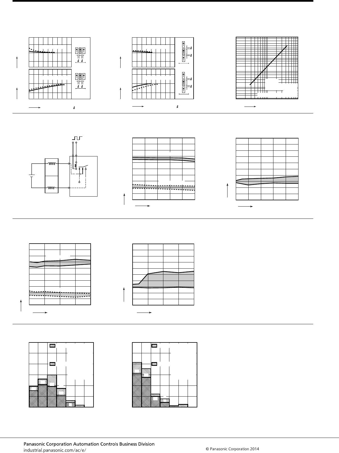
1. Maximum switching capacity 2. Life curve 3. Mechanical life
Tested sample: TQ2-12V, 10 pcs.
30 100 200
1.0
0.5
0.4
0.3
0.2
Switching voltage,V
Switching current, A
DC load (cosϕ=1)
AC load (cosϕ=1)
No. of operations, ×10
4
Switching current, A
100
10
0 0.5 1.0
30 V DC resistive load
125 V AC resistive load
Ratio against the rated voltage, %V
No. of operations, ×10
4
100
90
80
70
60
50
40
30
20
10
10
Max.
Min.
Max.
Min.
100 1,000 10,000
0
Pick-up voltage
Drop-out voltage
4.-(1) Electrical life (DC load)
Tested sample: TQ2-12V, 6 pcs.
Condition: 1 A 30 V DC resistive load, 20 cpm
Change of pick-up and drop-out voltage Change of contact resistance
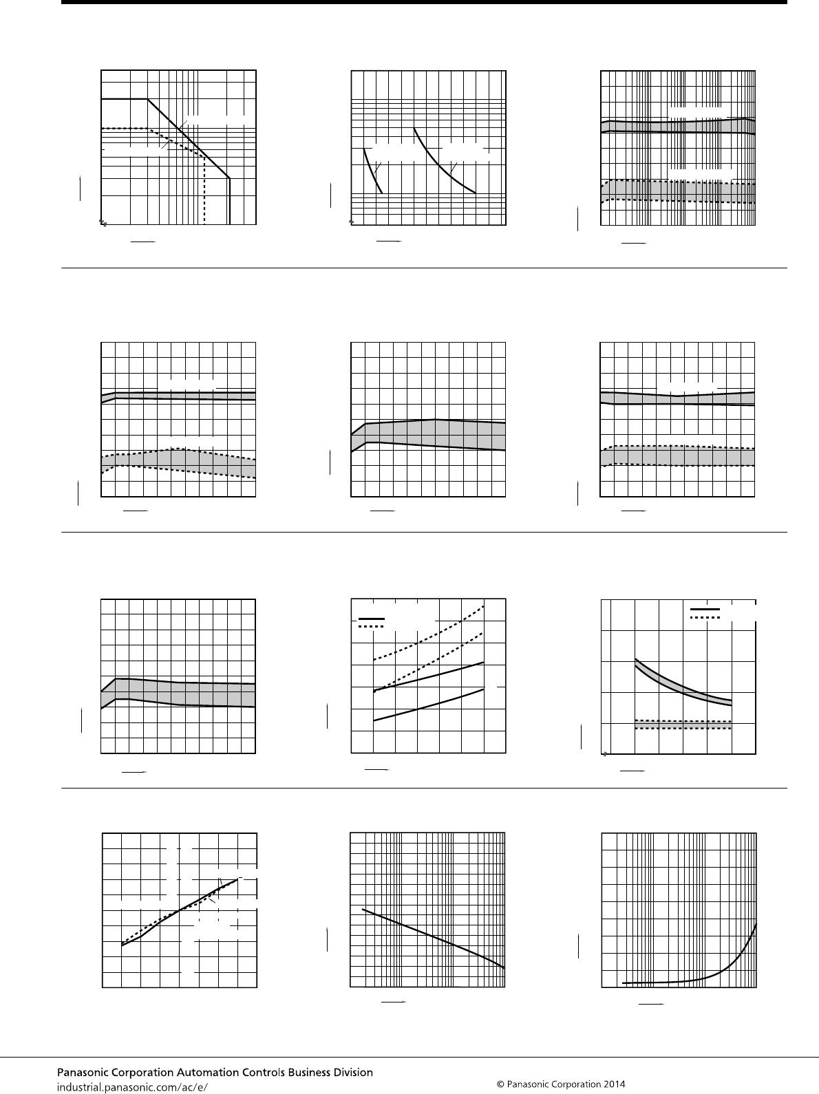
4.-(2) Electrical life (AC load)
Tested sample: TQ2-12V, 6 pcs.
Condition: 0.5 A 125 V AC resistive load, 20 cpm
Change of pick-up and drop-out voltage
100
90
80
70
60
50
40
30
20
10
01052015
No. of operations, ×10
4
Max.
Min.
Max.
Min.
Pick-up voltage
Drop-out voltage
Ratio against the rated voltage, %V
0 5 10 15 20
No. of operations, ×10
4
100
90
80
70
60
50
40
30
20
10
Contact resistance, mΩ
Max.
Min.
No. of operations, ×10
4
100
90
80
70
60
50
40
30
20
10
0510
Max.
Min.
Max.
Min.
Pick-up voltage
Drop-out voltage
Ratio against the rated voltage, %V
Change of contact resistance
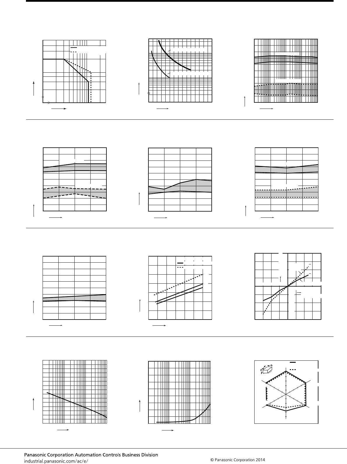
5. Coil temperature rise (2C)
Tested sample: TQ2-12V
Measured portion: Inside the coil
Ambient temperature: 30°C 86°F
6. Ambient temperature characteristics
Tested sample: TQ2-12V, 5 pcs.
No. of operations, ×10
4
0510
100
90
80
70
60
50
40
30
20
10
Contact resistance, mΩ
Max.
Min.
1 A
1 A
Coil applied voltage, %V
100 110 120 130 140 150
70
60
50
40
30
20
10
0
Temperature rise, C°
0 A
3 to 12 V DC type
24 V DC type
Nominal coil voltage
Pick-up voltage
Drop-out
voltage
-30
-20
-10
-40
10
20
30
40
80604020
-40 -20 0
Ambient
temperature,°C
Variation ratio,%
x
x
7.-(1) High-frequency characteristics
(Isolation)
7.-(2) High-frequency characteristics
(Insertion loss)
8. Malfunctional shock (single side stable)
Tested sample: TQ2-12V, 6 pcs.
10 100 1,000
50
100
Frequency, MHz
Isolation, dB
Frequency, MHz
Insertion loss, dB
0.2
0.4
0.6
0.8
1.0
0 10 100 1,000
Y
,
Y
,
Y
Y
Z
,
Z
,
Z
Z
X
,
X
,
X
X
980m/s
2
980m/s
2
980m/s
2
980m/s
2
980m/s
2
980m/s
2
Deenergized
condition
Energized condition