Expand menu
0
Cart
Home
Products
Sensors
Semiconductors
Passive Components
Connectors
Power
Electromechanical
Optoelectronics
Circuit Protection
Integrated Circuits - ICs
Main Products
Manufacturers
Blog
Services
About OMO
About Us
Contact Us
Check Stock
IPS021S
P1-P3
P4-P6
P7-P9
P10-P12
IPS021(S)
www
.irf
.com
7
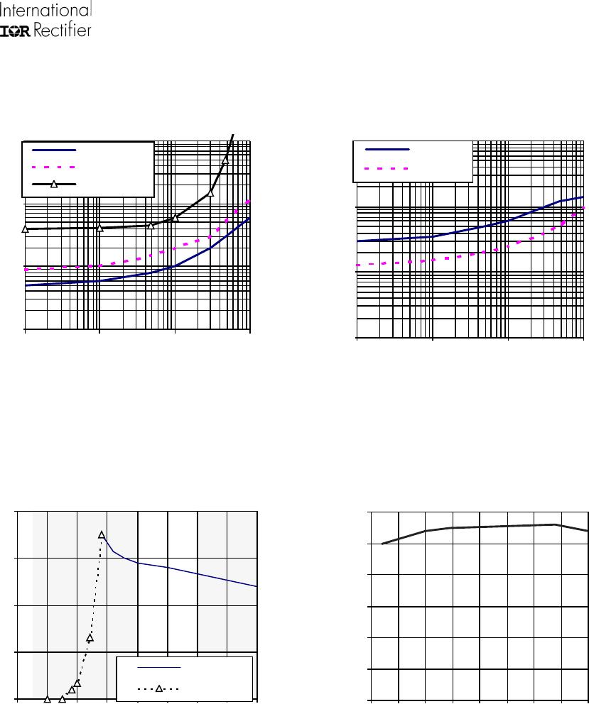
Figure 9 - Turn-ON Delay Time, Rise Time & Time
to 130% final Rds(on) (us) Vs IN Resistor (
Ω
)
Figure 10 - Turn-OFF Delay Time & Fall Time (us)
Vs IN Resistor (
Ω
)
0.
1
1
10
100
10
100
100
0
100
00
de
la
y on
ri
se ti
me
130%
r
d
s
on
0.
1
1
10
100
10
100
1000
10000
de
l
ay o
ff
fa
l
l ti
m
e
Figure 12 - I shutdown (A) Vs Temperature (
o
C)
Figure 11 - Current Iim. & I shutdown (A)
Vs Vin (V)
0
2
4
6
8
0123
45
678
Is
d
25°
C
Il
im
25°C
0
1
2
3
4
5
6
-
5
0
-
2
5
0
25
50
75
100
125
150
IPS021(S)
8
www
.irf
.com
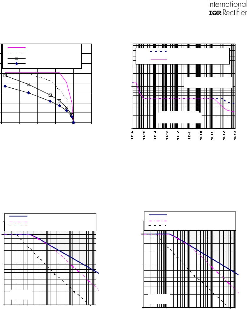
Figure 15b - Max. Iclamp (A) Vs Inductive Load
(mH) IPS021S
0.1
1
10
0.
01
0.
1
1
10
100
s
i
ngl
e
pul
s
e
100 H
z r
t
h
=
60
°
C
/W
dT=
25
°
C
1k
H
z
r
th
=6
0
°
C/W
dT=2
5
°
C
Vbat = 1
4 V
Tjini = T sd
Figure 14 - Ids (A) Vs Protection Resp. Time (s)
IPS021 & IPS021S
1
10
100
T=
25
°
C
S
t
d
.
footpr
int
T
=
100
°
C
S
td. foot
p
r
int
Current path capability
should be above this curve
Load characteristic should
be below this curve
Figure 15a - Iclamp (A) Vs Inductive Load (mH)
IPS021
Figure 13 - Max.Cont. Ids (A)
Vs Amb. Temperature (
o
C) IPS021/IPS021S
0.1
1
10
0.
01
0.
1
1
10
100
si
n
g
l
e p
u
l
se m
a
x
.
c
u
rren
t
100 H
z r
t
h
=
60
°
C
/W
dT=
2
5
°
C
1k
H
z
r
th
=
60
°
C
/
W dT=
25
°
C
Vbat =
14 V
Tjin
i = T
s
d
0
1
2
3
4
5
6
7
8
-50
0
50
100
150
200
rt
h
=
5
°
C/W
rt
h
=
1
5
°
C/W
1
"
f
ootpr
i
nt
35
°
C/W
s
td.
footpr
i
nt 60
°
C/
W
IPS021(S)
www
.irf
.com
9
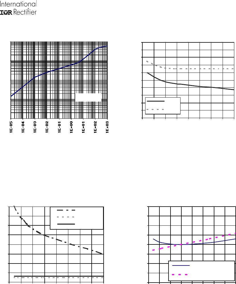
Figure 16 - Transient Thermal Imped. (
o
C/W)
Vs Time (s)
0.
01
0.
1
1
10
100
Single pulse
Figure 17 - Input Current (uA) Vs
Junction Temperature (
o
C)
0
20
40
60
80
100
120
140
160
180
200
-
5
0
-
25
0
25
50
75
100
125
150
I
in,
on
I
in,
off
0
2
4
6
8
10
12
14
16
-
5
0
-
2
5
0
25
50
75
100
125
150
T
reset
ri
se t
i
m
e
fa
ll
ti
m
e
Figure 18 - Rise Time, Fall Time and Treset (
µ
s)
Vs Tj (
o
C)
Figure 19 -Vin clamp and Vds clamp (%) Vs
Tj (
o
C)
80%
85%
90%
95%
100%
105%
110%
115%
120%
-
5
0
-
2
5
0
2
55
07
5
1
0
0
1
2
5
1
5
0
Vds
clamp @
Isd
Vin
clamp @
10m
A
P1-P3
P4-P6
P7-P9
P10-P12
IPS021S
Mfr. #:
Buy IPS021S
Manufacturer:
Infineon Technologies
Description:
Gate Drivers IR_HSS-LSS-GATEDRIVER
Lifecycle:
New from this manufacturer.
Delivery:
DHL
FedEx
Ups
TNT
EMS
Payment:
T/T
Paypal
Visa
MoneyGram
Western
Union
Products related to this Datasheet
IPS021S
IPS021STRL
IPS021