ADC0808S125_ADC0808S250_3 © NXP B.V. 2009. All rights reserved.
Product data sheet Rev. 03 — 24 February 2009 11 of 23
NXP Semiconductors
ADC0808S125/250
Single 8-bit ADC, up to 125 MHz or 250 MHz
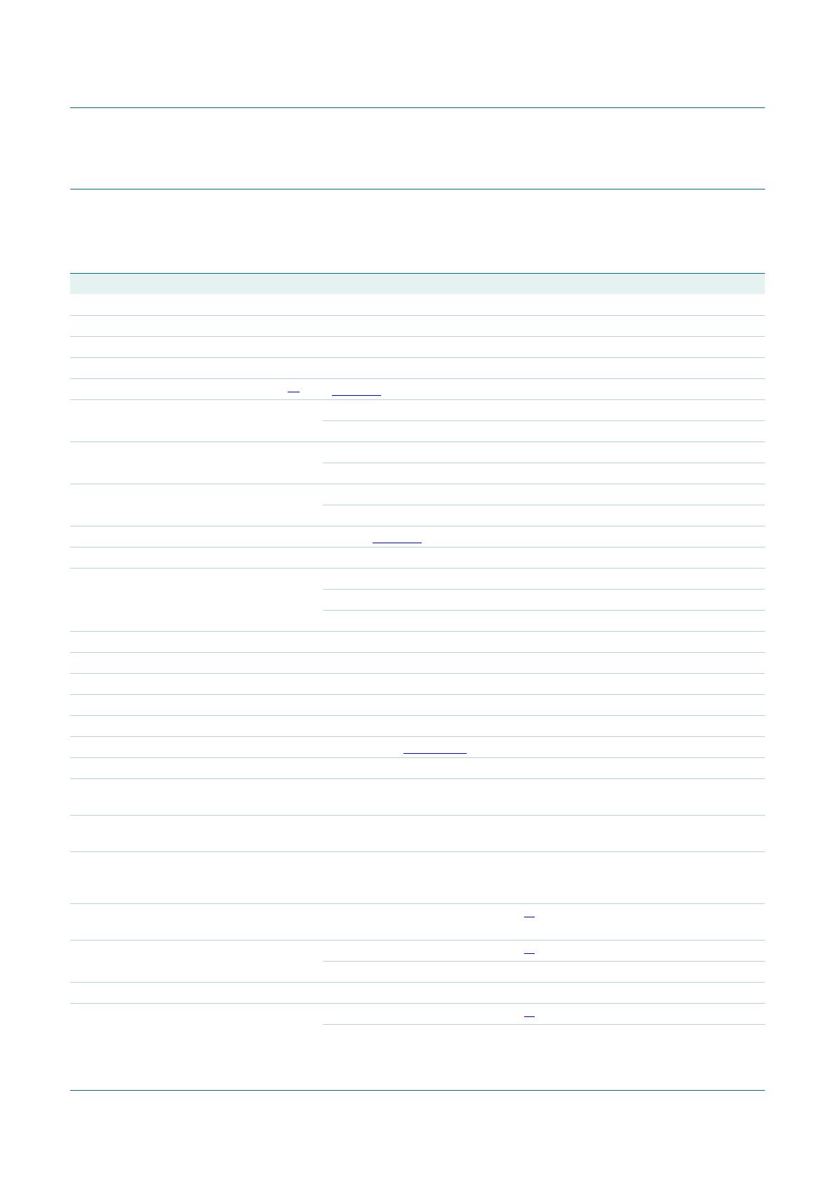
[1] Guaranteed by design.
[2] |V
gpd
| is the voltage of ground potential difference across or between boards.
[3] The ADC input range can be adjusted with an external reference voltage applied to pin FSIN. This voltage must be referenced to AGND.
V
idth
input differential threshold voltage |V
gpd
| < 50 mV
[2]
−100 - +100 mV
I
I
input current 825 mV < V
I
< 1575 mV - - 50 µA
1.8 V CMOS clock input; see
Figure 4
V
IL
LOW-level input voltage DGND - 0.2V
CCD
V
V
IH
HIGH-level input voltage 0.8V
CCD
-V
CCD
V
I
IL
LOW-level input current V
IL
= 0.2V
CCD
--50µA
I
IH
HIGH-level input current V
IH
= 0.8V
CCD
--50µA
Analog inputs: pins IN and INN
R
i
input resistance
[1]
- 1.0 - MΩ
C
i
input capacitance
[1]
- 1.0 - pF
V
I(cm)
common-mode input voltage V
i(IN)
=V
i(INN)
;
output code = 127
0.7 0.95 1.0 V
Digital input pins: OTC, CE_N, DEL0, DEL1, CLKSEL and CCSSEL
V
IL
LOW-level input voltage DGND - 0.2V
CCD
V
V
IH
HIGH-level input voltage 0.8V
CCD
-V
CCD
V
I
IL
LOW-level input current V
IL
= 0.3V
CCD
--50µA
I
IH
HIGH-level input current V
IH
= 0.7V
CCD
--50µA
Voltage controlled regulator output: pin CMADC
V
O(cm)
common-mode output voltage 0.85 0.95 1.1 V
Reference voltage input: pin FSIN
[3]
V
FSIN
voltage on pin FSIN internal reference - 0 0.6 V
external reference 1.15 1.25 1.35 V
I
i(FSIN)
input current on pin FSIN - 12 - µA
V
i(p-p)(max)
maximum peak-to-peak input
voltage
internal reference 1.92 2 2.03 V
external reference
V
FSIN
= 1.15 V 1.80 1.825 1.85 V
V
FSIN
= 1.25 V 1.98 1.99 2.03 V
V
FSIN
= 1.35 V 2.11 2.16 2.18 V
Digital outputs: pins D0 to D7, CCS and IR
V
OL
LOW-level output voltage OGND - 0.2 V
V
OH
HIGH-level output voltage V
CCO
− 0.2 - V
CCO
V
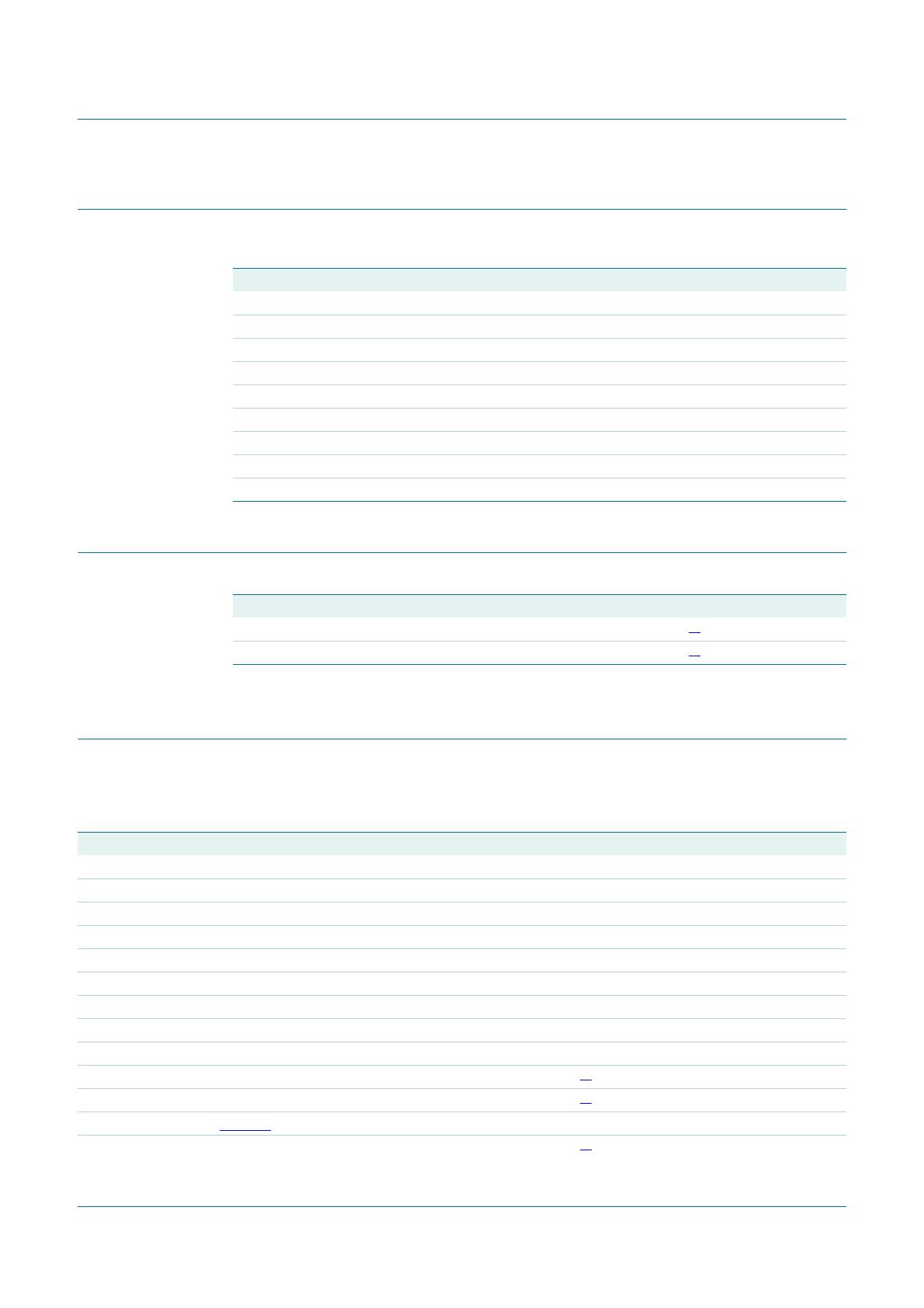
Table 12. Static characteristics
…continued
V
CCA
= 3.0 V to 3.6 V; V
CCD
= 1.65 V to 1.95 V; V
CCO
= 1.65 V to 1.95 V; pins AGND1, AGND2 and DGND1 shorted together;
T
amb
=
−
40
°
C to +85
°
C; V
i(IN)
−
V
i(INN)
= 2.0 V
−
0.5 dB; V
I(cm)
= 0.95 V; V
FSIN
= 0 V; typical values are measured at
V
CCA
= 3.3 V, V
CCD
=V
CCO
= 1.8 V, T
amb
=25
°
C and C
L
= 10 pF; unless otherwise specified.
Symbol Parameter Conditions Min Typ Max Unit