12
R1 - Is the Over-Current sense resistor. If the input current is
high enough, such that the voltage drop across R1 exceeds
the SENSE comparator trip point (50mV nominal), the GATE
pin will be pulled lower (to ~4V) and current will be regulated
to 50mV/Rsense for approximately 600s. The Over-Current
threshold is defined in Equation 3 below. If the 600s time-
out period is exceeded the Over-Current latch will be set and
the FET will be turned off to protect the load from excessive
current. A typical value for R1 is 0.02which sets an Over-
Current trip point of; I
OC
= V/R = 0.05/0.02 = 2.5 Amps. To
select the appropriate value for R1, the user must first
determine at what level of current it should trip, take into
account worst case variations for the trip point (50mV
10mV = 20%), and the tolerances of the resistor (typically
1% or 5%). Note that the Over-Current threshold should be
set above the inrush current level plus the expected load
current to avoid activating the current limit and time-out
circuitry during start-up. If the power good output is used to
enable an external module, the desired inrush current only
needs to be considered. One rule of thumb is to set the
Over-Current threshold 2-3 times higher than the normal
operating current.
Physical layout of R1 SENSE resistor is critical to avoid
the possibility of false over current events. Since it is in the
main input-to-output path, the traces should be wide enough
to support both the normal current, and up to the over-
current trip point. Ideally trace routing between the R1
resistor and the ISL6141/51 (pin 4 (V
EE
) and pin 5 (SENSE)
is direct and as short as possible with zero current in the
sense lines. (See Figure 24).
CL - is the sum of all load capacitances, including the load’s
input capacitance itself. Its value is usually determined by
the needs of the load circuitry, and not the hot plug (although
there can be interaction). For example, if the load is a
regulator, then the capacitance may be chosen based on the
input requirements of that circuit (holding regulation under
current spikes or loading, filtering noise, etc.) The value
chosen will affect the peak inrush current. Note that in the
case of a regulator, there may be capacitors on the output of
that circuit as well; these need to be added into the
capacitance calculation during inrush (unless the regulator is
delayed from operation by the PWRGD signal).
RL - is the equivalent resistive value of the load and
determines the normal operation current delivered through
the FET. It also affects some dynamic conditions (such as
the discharge time of the load capacitors during a power-
down). A typical value might be 48 (I = V/R = 48/48 = 1A).
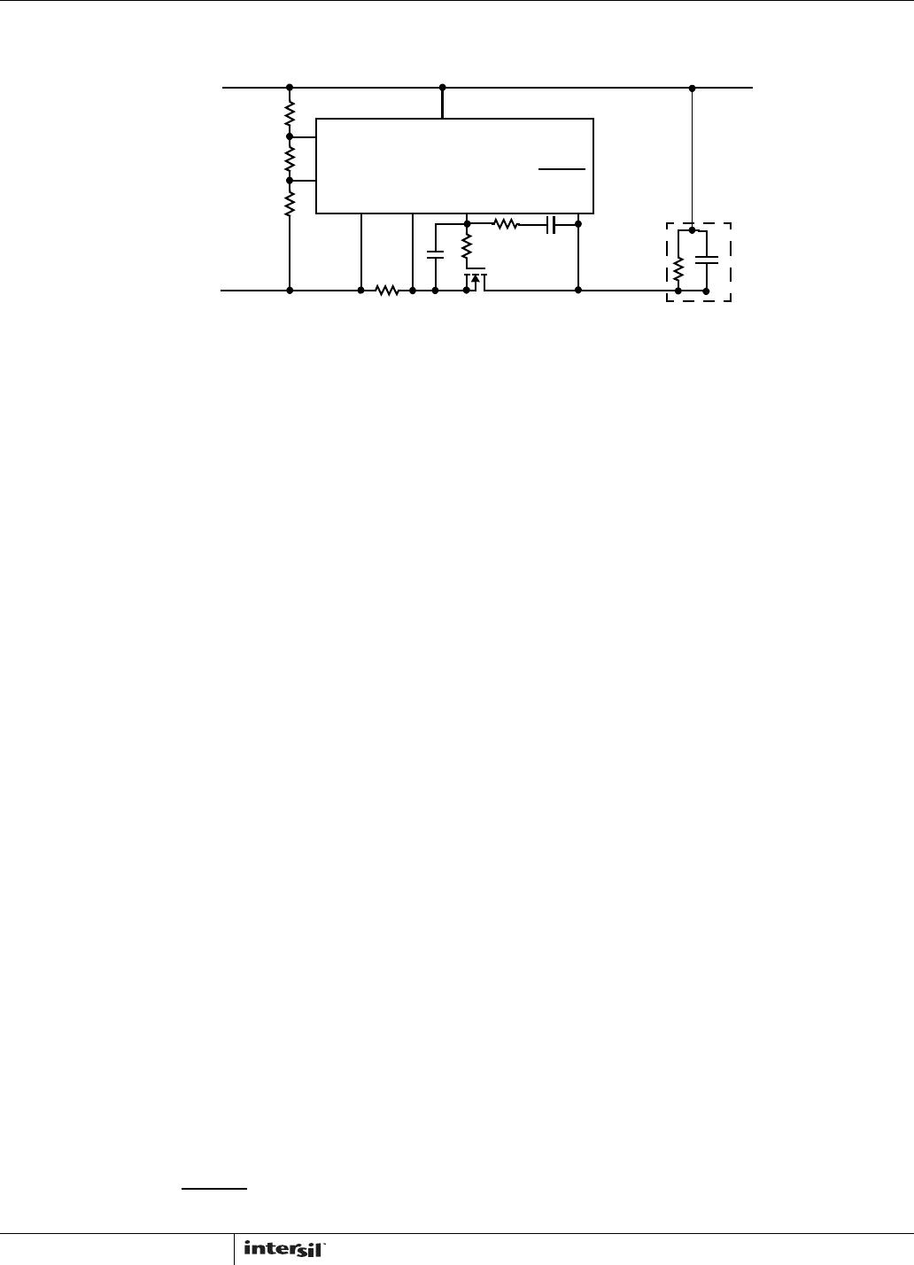
R2, C1, R3, C2 - are related to the GATE driver, as it
controls the inrush current.
R2 prevents high frequency oscillations; 10 is a typical
value. R2 = 10.
R3 and C2 act as a feedback network to control the inrush
current as shown in equation 4 below, where CL is the load
capacitance (including module input capacitance), and I
PU
is
the GATE pin charging current, nominally 50A.
Begin by choosing a value of acceptable inrush current for
the system, and then solve for C2.
C1 and R3 prevent Q1 from turning on momentarily when
power is first applied. Without them, C2 would pull the gate
of Q1 up to a voltage roughly equal to V
EE
*C2/Cgs(Q1)
(where Cgs is the FET gate-source capacitance) before the
ISL6141/2 could power up and actively pull the gate low.
Place C1 in parallel with the gate capacitance of Q1; isolate
them from C2 by R3.
C1= [(Vinmax - Vth)/Vth] * (C2+Cgd) - where Vth is the
FET’s minimum gate threshold, Vinmax is the maximum
operating input voltage, and Cgd is the FET gate-drain
capacitance.
R3 - its value is not critical, a typical value of 18k is
recommended but values down to 1K can be used. Lower
values of R3 will add delay to the gate turn-on for hot
insertion and the single retry event following a hard fault.
Note that although this IC was designed for -48V systems, it
can also be used as a low-side switch for positive 48V
systems; the operation and components are usually similar.
One possible difference is the kind of level shifting that may
be needed to interface logic signals to the UV input (to reset
the latch) or PWRGD output. For example, many of the IC
functions are referenced to the IC substrate, connected to
the V
EE
pin. But this pin may be considered -48V or GND,
depending upon the polarity of the system. And input or
output logic (running at 5V or 3.3V or even lower) might be
externally referenced to either V
DD
or V
EE
of the IC, instead
of GND.
I
OC
50mv
R
sense
--------------------=
(EQ. 3)
CORRECT
To SENSE
CURRENT
SENSE RESISTOR
INCORRECT
and V
EE
FIGURE 24. SENSE RESISTOR LAYOUT GUIDELINES
I
inrush
I
PU
C
L
C
2
-------=
(EQ. 4)
ISL6141, ISL6151