AD8603/AD8607/AD8609
Rev. C | Page 13 of 16
PROXIMITY SENSORS
Proximity sensors can be capacitive or inductive and are used in
a variety of applications. One of the most common applications
is liquid level sensing in tanks. This is particularly popular in
pharmaceutical environments where a tank must know when to
stop filling or mixing a given liquid. In aerospace applications,
these sensors detect the level of oxygen used to propel engines.
Whether in a combustible environment or not, capacitive
sensors generally use low voltage. The precision and low voltage
of the AD8603/AD8607/AD8609 make the parts an excellent
choice for such applications.
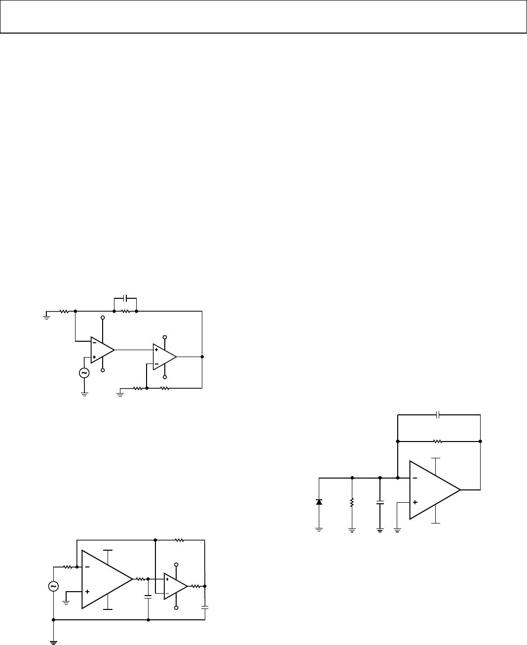
COMPOSITE AMPLIFIERS
A composite amplifier can provide a very high gain in applications
where high closed-loop dc gains are needed. The high gain
achieved by the composite amplifier comes at the expense of a
loss in phase margin. Placing a small capacitor, C
F
, in the feedback
in parallel with R2 (see Figure 45) improves the phase margin.
Picking C
F
= 50 pF yields a phase margin of about 45° for the
values shown in Figure 45.
V
EE
V
CC
R1
C
F
1kΩ
V
CC
V
EE
V
IN
99kΩ
R2
AD8603
AD8541
V+
V
–
V+
V
–
R3 R4
99kΩ1kΩ
U5
04356-045
Figure 45. High Gain Composite Amplifier
A composite amplifier can be used to optimize dc and ac
characteristics. Figure 46 shows an example using the AD8603
and the AD8541. This circuit offers many advantages. The band-
width is increased substantially, and the input offset voltage and
noise of the AD8541 become insignificant because they are divided
by the high gain of the AD8603.
The circuit in Figure 46 offers high bandwidth (nearly double
that of the AD8603), high output current, and very low power
consumption of less than 100 μA.
R1
1kΩ
V+
V
–
V
IN
100kΩ
R2
AD8541
100Ω
C3
1kΩ
R4
R3
C2
V
CC
V
EE
04356-046
V
CC
V
EE
V–
V+
AD8603
Figure 46. Low Power Composite Amplifier
BATTERY-POWERED APPLICATIONS
The AD8603/AD8607/AD8609 are ideal for battery-powered
applications. The parts are tested at 5 V, 3.3 V, 2.7 V, and 1.8 V
and are suitable for various applications whether in single or
dual supply.
In addition to their low offset voltage and low input bias, the
AD8603/AD8607/AD8609 have a very low supply current of
40 μA, making the parts an excellent choice for portable electronics.
The TSOT package allows the AD8603 to be used on smaller
board spaces.
PHOTODIODES
Photodiodes have a wide range of applications from barcode
scanners to precision light meters and CAT scanners. The very
low noise and low input bias current of the AD8603/AD8607/
AD8609 make the parts very attractive amplifiers for I-V
conversion applications.
Figure 47 shows a simple photodiode circuit. The feedback
capacitor helps the circuit maintain stability. The signal band-
width can be increased at the expense of an increase in the total
noise; a low-pass filter can be implemented by a simple RC network
at the output to reduce the noise. The signal bandwidth can be
calculated by ½πR2C2, and the closed-loop bandwidth is the
intersection point of the open-loop gain and the noise gain.
The circuit shown in Figure 47 has a closed-loop bandwidth of
58 kHz and a signal bandwidth of 16 Hz. Increasing C2 to 50 pF
yields a closed-loop bandwidth of 65 kHz, but only 3.2 Hz of
signal bandwidth can be achieved.
C2
10pF
R2
1000MΩ
R1
1000MΩ
V
CC
V
EE
V–
V+
AD8603
C1
10pF
04356-047
Figure 47. Photodiode Circuit