ADuM3400W/ADuM3401W/ADuM3402W Data Sheet
V
DD1
1
*GND
1
2
V
IA
3
V
IB
4
V
DD2
16
GND
2
*
15
V
OA
14
V
OB
13
V
OC
5
V
IC
12
V
OD
6
V
ID
11
V
E1
7
V
E2
10
*GND
1
8
GND
2
*
9
ADuM3402W
TOP VIEW
(Not to Scale)
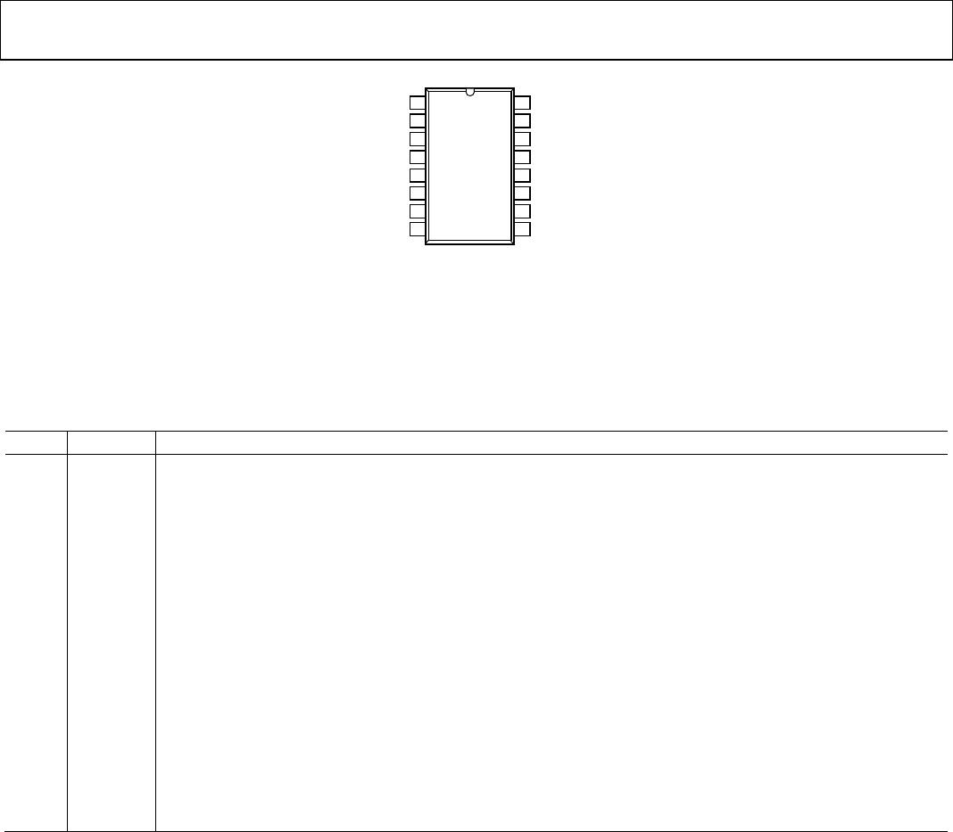
*PIN 2 AND PIN 8 ARE INTERNALLY CONNECTED AND CONNECTING
BOTH TO GND
1
IS RECOMMENDED. PIN 9 AND PIN 15 ARE INTERNALLY
CONNECTED AND CONNECTING BOTH TO GND
2
IS RECOMMENDED.
IN NOISY ENVIRONMENTS, CONNECTING OUTPUT ENABLES (PIN 7 FOR
ADuM3401W/ADuM3402W AND PIN 10 FOR ALL MODELS) TO AN EXTERNAL
LOGIC HIGH OR LOW IS RECOMMENDED.
11000-007
Figure 7. ADuM3402W Pin Configuration
Table 23. ADuM3402W Pin Function Descriptions
Pin No. Mnemonic Description
1 V
DD1
Supply Voltage for Isolator Side 1, 3.135 V to 5.5 V.
2, 8 GND
1
Ground 1. Ground reference for Isolator Side 1.
3 V
IA
Logic Input A.
4 V
IB
Logic Input B.
5 V
OC
Logic Output C.
6 V
OD
Logic Output D.
7 V
E1
Output Enable 1. Active high logic input. V
OC
and V
OD
outputs are enabled when V
E1
is high or disconnected.
V
OC
and V
OD
outputs are disabled when V
E1
is low. In noisy environments, connecting V
E1
to an external logic high or
low is recommended.
9, 15 GND
2
Ground 2. Ground reference for Isolator Side 2.
10 V
E2
Output Enable 2. Active high logic input. V
OA
and V
OB
outputs are enabled when V
E2
is
high or disconnected.
V
OA
and V
OB
outputs are disabled when V
E2
is low. In noisy environments, connecting V
E2
to an external logic high or
low is recommended.
11 V
ID
Logic Input D.
12 V
IC
Logic Input C.
13 V
OB
Logic Output B.
14 V
OA
Logic Output A.
16 V
DD2
Supply Voltage for Isolator Side 2, 3.135 V to 5.5 V.
Rev. B | Page 12 of 20

