LTC1069-7
6
10697fa
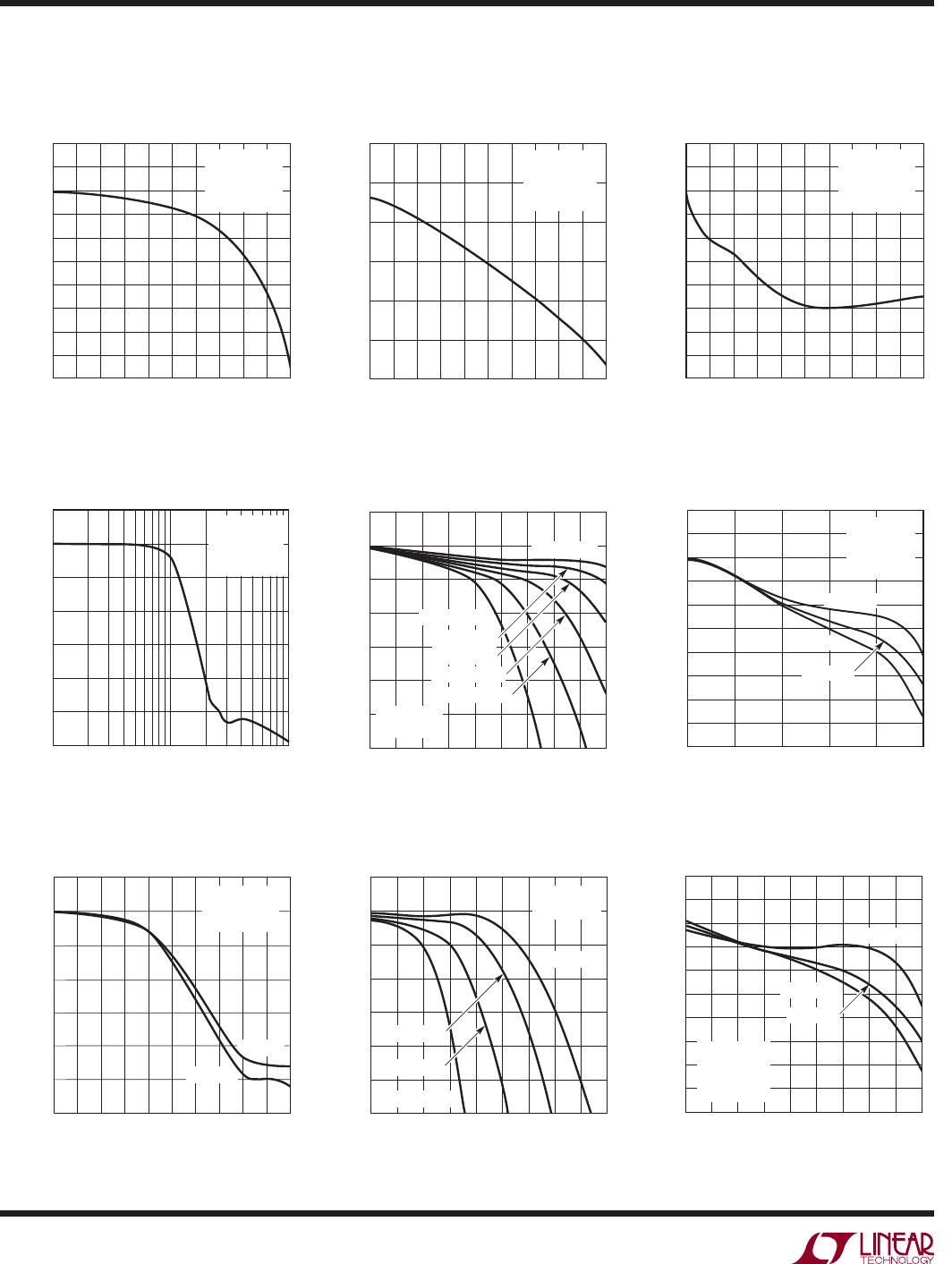
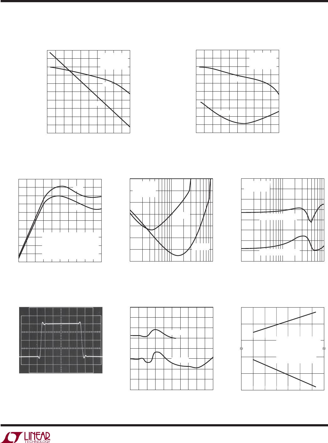
TYPICAL PERFORMANCE CHARACTERISTICS
Output Voltage Swing
vs Temperature
Supply Current
vs Supply Voltage
Supply Current
vs Clock Frequency
PIN FUNCTIONS
AGND (Pin 1): Analog Ground. The quality of the analog
signal ground can affect the fi lter performance. For either
single or dual supply operation, an analog ground plane
surrounding the package is recommended. The analog
ground plane should be connected to any digital ground
at a single point. For dual supply operation, Pin 1 should
be connected to the analog ground plane.
For single supply operation, Pin 1 should be bypassed
to the analog ground plane with a capacitor 0.47μF or
larger. An internal resistive divider biases Pin 1 to half the
total power supply. Pin 1 should be buffered if used to
bias other ICs. Figure 1 shows the connections for single
supply operation.
V
+
, V
–
(Pins 2, 7): Power Supplies. The V
+
(Pin 2) and
V
–
(Pin 7) should be bypassed with a 0.1μF capacitor to
an adequate analog ground. The fi lter’s power supplies
should be isolated from other digital or high voltage analog
supplies. A low noise linear supply is recommended. Using
switching power supplies will lower the signal-to-noise
ratio of the fi lter. Unlike previous monolithic fi lters, the
power supplies can be applied in any order, that is, the
positive supply can be applied before the negative supply
and vice versa. Figure 2 shows the connections for dual
supply operation.
NC (Pins 3, 6):
No Connection. Pins 3 and 6 are not
connected to any internal circuitry; they should be tied
to ground.
V
IN
(Pin 4): Filter Input. The fi lter input pin is internally
connected to the inverting inputs of two op amps through
a 36k resistor for each op amp. This parallel combination
creates an 18k input impedance.
TEMPERATURE (°C)
–40
–4.7
VOLTAGE SWING (V)
–4.5
4.2
0
40
60
1069-7 G18
–4.6
4.1
4.0
–20
20
80
100
V
S
= ±5V
f
CLK
= 2.5MHz
f
CUTOFF
= 100kHz
R
L
= 10k
I
SOURCE
/I
SINK
= 1mA
SUPPLY VOLTAGE (±V)
0
SUPPLY CURRENT (mA)
12
1069-7 G19
36
25
20
15
10
5
0
45
85°C
–40°C
25°C
f
CLK
= 10Hz
CLOCK FREQUENCY (MHz)
0.25 1.25 2.25 3.25 4.25 5.25
SUPPLY CURRENT (mA)
1069-7 G20
22
21
20
19
18
17
16
15
14
13
12
11
10
V
S
= ±5V
V
S
= 5V
1069-7 F01
1k
V
+
LTC1069-7
CLOCK
SOURCE
0.47μF
0.1μF
ANALOG GROUND
PLANE
8
7
6
5
1
2
3
4
STAR
SYSTEM
GROUND
DIGITAL
GROUND
PLANE
AGND
V
+
NC
V
IN
V
OUT
V
–
NC
CLK
V
OUT
V
IN
Figure 1. Connections for Single Supply Operation