MAX492/MAX494/MAX495
Single/Dual/Quad, Micropower,
Single-Supply Rail-to-Rail Op Amps
12 ______________________________________________________________________________________
in series with IN-, IN+, or both. Series resistors are not
recommended for amplifier applications, as they may
increase input offsets and decrease amplifier bandwidth.
Output Loading and Stability
Even with their low quiescent current of less than 150µA
per op amp, the MAX492/MAX494/MAX495 are well
suited for driving loads up to 1k while maintaining DC
accuracy. Stability while driving heavy capacitive loads
is another key advantage over comparable CMOS rail-
to-rail op amps.
In op amp circuits, driving large capacitive loads
increases the likelihood of oscillation. This is especially
true for circuits with high loop gains, such as a unity-
gain voltage follower. The output impedance and a
capacitive load form an RC network that adds a pole to
the loop response and induces phase lag. If the pole
frequency is low enough—as when driving a large
capacitive load—the circuit phase margin is degraded,
leading to either an under-damped pulse response or
oscillation.
10µs/div
V
IN
50mV/div
V
OUT
50mV/div
10µs/div
V
IN
50mV/div
V
OUT
50mV/div
10µs/div
V
IN
50mV/div
V
OUT
50mV/div
Figure 7c. MAX492 Voltage Follower with 500pF Load—
R
L
=
Figure 7a. MAX492 Voltage Follower with 500pF Load—
R
L
= 5k
Figure 7b. MAX492 Voltage Follower with 500pF Load—
R
L
= 20k
V
IN
50mV/div
V
OUT
50mV/div
10µs/div
Figure 6. MAX492 Voltage Follower with 1000pF Load
(R
L
=
)
The MAX492/MAX494/MAX495 can drive capacitive
loads in excess of 1000pF under certain conditions
(Figure 5). When driving capacitive loads, the greatest
potential for instability occurs when the op amp is
sourcing approximately 100µA. Even in this case, sta-
bility is maintained with up to 400pF of output capaci-
tance. If the output sources either more or less current,
stability is increased. These devices perform well with a
1000pF pure capacitive load (Figure 6). Figure 7 shows
the performance with a 500pF load in parallel with vari-
ous load resistors.
To increase stability while driving large capacitive
loads, connect a pull-up resistor at the output to
decrease the current that the amplifier must source. If
the amplifier is made to sink current rather than source,
stability is further increased.
Frequency stability can be improved by adding an out-
put isolation resistor (R
S
) to the voltage-follower circuit
(Figure 8). This resistor improves the phase margin of
the circuit by isolating the load capacitor from the op
amp’s output. Figure 9a shows the MAX492 driving
10,000pF (R
L
100k), while Figure 9b adds a 47
isolation resistor.
MAX492/MAX494/MAX495
Single/Dual/Quad, Micropower,
Single-Supply Rail-to-Rail Op Amps
______________________________________________________________________________________ 13
V
IN
50mV/div
V
OUT
50mV/div
10µs/div
V
IN
50mV/div
V
OUT
50mV/div
10µs/div
MAX495
V
OUT
V
CC
2
3
1k
1k
+5V
7
4
6
MAX49_
V
OUT
V
IN
C
L
R
S
Figure 10. Power-Up Test Configuration
Figure 9b. Driving a 10,000pF Capacitive Load with a 47
Isolation Resistor
Figure 9a. Driving a 10,000pF Capacitive Load
Figure 8. Capacitive-Load Driving Circuit
MAX492/MAX494/MAX495
Because the MAX492/MAX494/MAX495 have excellent
stability, no isolation resistor is required, except in the
most demanding applications. This is beneficial
because an isolation resistor would degrade the low-
frequency performance of the circuit.
Power-Up Settling Time
The MAX492/MAX494/MAX495 have a typical supply
current of 150µA per op amp. Although supply current is
already low, it is sometimes desirable to reduce it further
by powering down the op amp and associated ICs for
periods of time. For example, when using a MAX494 to
buffer the inputs to a multi-channel analog-to-digital con-
verter (ADC), much of the circuitry could be powered
down between data samples to increase battery life. If
samples are taken infrequently, the op amps, along with
the ADC, may be powered down most of the time.
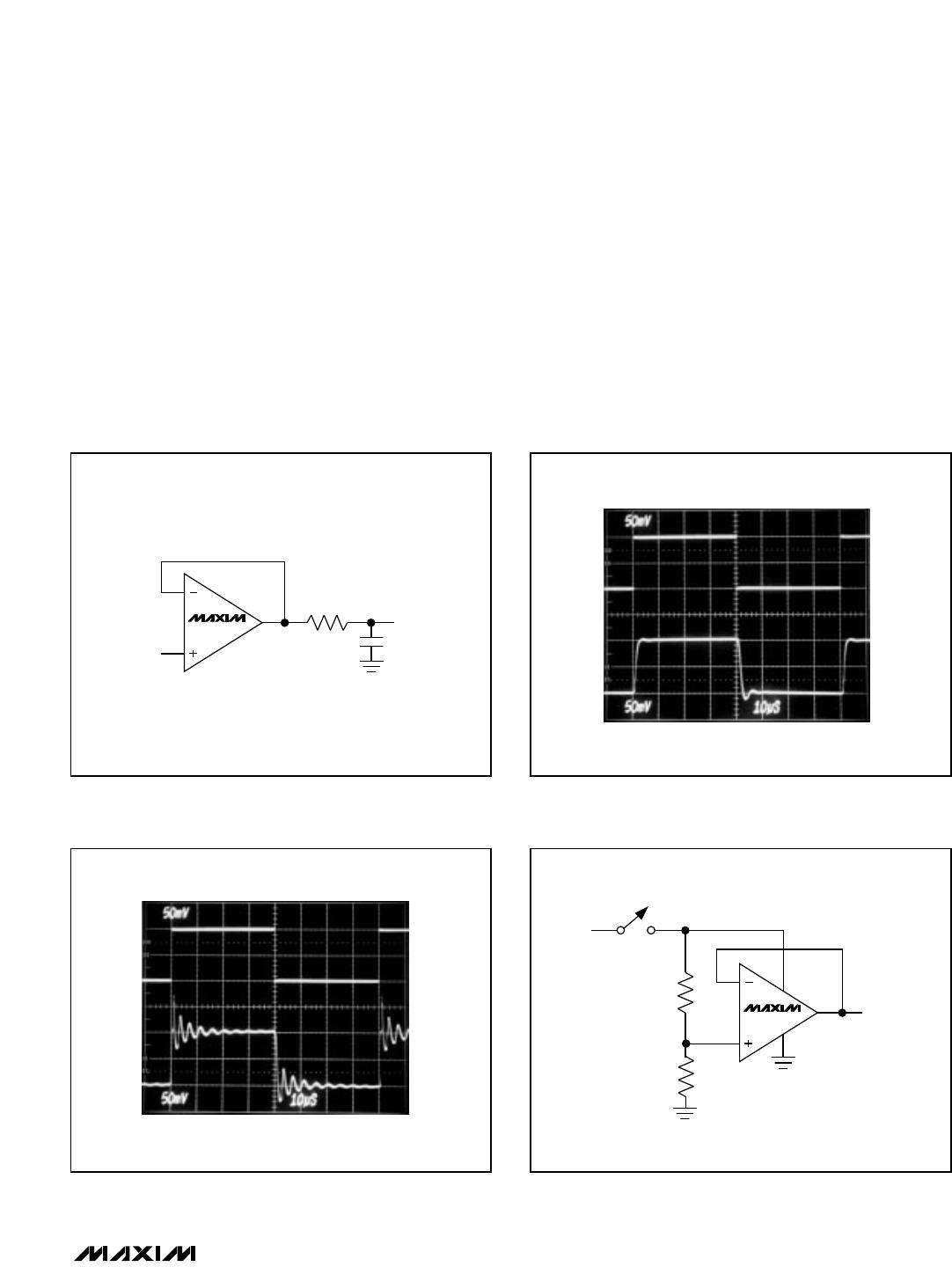
When power is reapplied to the MAX492/MAX494/
MAX495, it takes some time for the voltages on the sup-
ply pin and the output pin of the op amp to settle.
Supply settling time depends on the supply voltage, the
value of the bypass capacitor, the output impedance of
the incoming supply, and any lead resistance or induc-
tance between components. Op amp settling time
depends primarily on the output voltage and is slew-rate
limited. With the noninverting input to a voltage follower
held at mid-supply (Figure 10), when the supply steps
from 0V to V
CC
, the output settles in approximately 4µs
for V
CC
= +3V (Figure 11a) or 10µs for V
CC
= +5V
(Figure 11b).
Power Supplies and Layout
The MAX492/MAX494/MAX495 operate from a single
2.7V to 6V power supply, or from dual supplies of
±1.35V to ±3V. For single-supply operation, bypass the
power supply with a 1µF capacitor in parallel with a
0.1µF ceramic capacitor. If operating from dual sup-
plies, bypass each supply to ground.
Good layout improves performance by decreasing the
amount of stray capacitance at the op amp’s inputs and
output. To decrease stray capacitance, minimize both
trace lengths and resistor leads and place external
components close to the op amp’s pins.
Rail-to-Rail Buffers
The
Typical Operating Circuit
shows a MAX495 gain-of-
two buffer driving the analog input to a MAX187 12-bit
ADC. Both devices run from a single 5V supply, and the
converter’s internal reference is 4.096V. The MAX495’s
typical input offset voltage is 200µV. This results in an
error at the ADC input of 400µV, or less than half of one
least significant bit (LSB). Without offset trimming, the
op amp contributes negligible error to the conversion
result.
Single/Dual/Quad, Micropower,
Single-Supply Rail-to-Rail Op Amps
14 ______________________________________________________________________________________
V
CC
1V/div
V
OUT
500mV/div
5µs/div
V
CC
2V/div
V
OUT
1V/div
5µs/div
Figure 11b. Power-Up Settling Time (V
CC
= +5V)Figure 11a. Power-Up Settling Time (V
CC
= +3V)

MAX494CSD-T

Mfr. #:
Manufacturer:
Maxim Integrated
Description:
Operational Amplifiers - Op Amps uPower Single-Supply Rail-Rail
Lifecycle:
New from this manufacturer.
Delivery:
DHL FedEx Ups TNT EMS
Payment:
T/T Paypal Visa MoneyGram Western Union