Design and specifications are each subject to change without notice. Ask factory for the current technical specifications before purchase and/or use.
Should a safety concern arise regarding this product, please be sure to contact us immediately.
Power Inductors
I
DC
(A)
0.0
0.5
1.0
1.5
2.5
2.0
0105 1520253035404550
Inductance (µH)
I
DC
(A)
0.0
0.5
1.0
1.5
2.0
0105 1520253035404550
Inductance (µH)
I
DC
(A)
0
1
2
3
4
5
0105152025303540
Inductance (µH)
0.0
0.1
0.2
0.3
0.4
010 20304050 807060
Inductance (µH)
I
DC
(A)
Inductance (µH)
I
DC
(A)
0.0
0.1
0.2
0.3
0.4
0.5
0.7
0.6
0102030405060
I
DC
(A)
0.0
0.2
0.4
0.6
0.8
1.2
1.0
0102030405060
Inductance (µH)
Inductance (µH)
I
DC
(A)
0.0
0.5
1.0
1.5
2.0
2.5
3.0
010203040
0.0
0.5
1.0
1.5
2.0
2.5
3.5
3.0
05 1510 20 25 30 35 40
Inductance (µH)
I
DC
(A)
Standard Parts
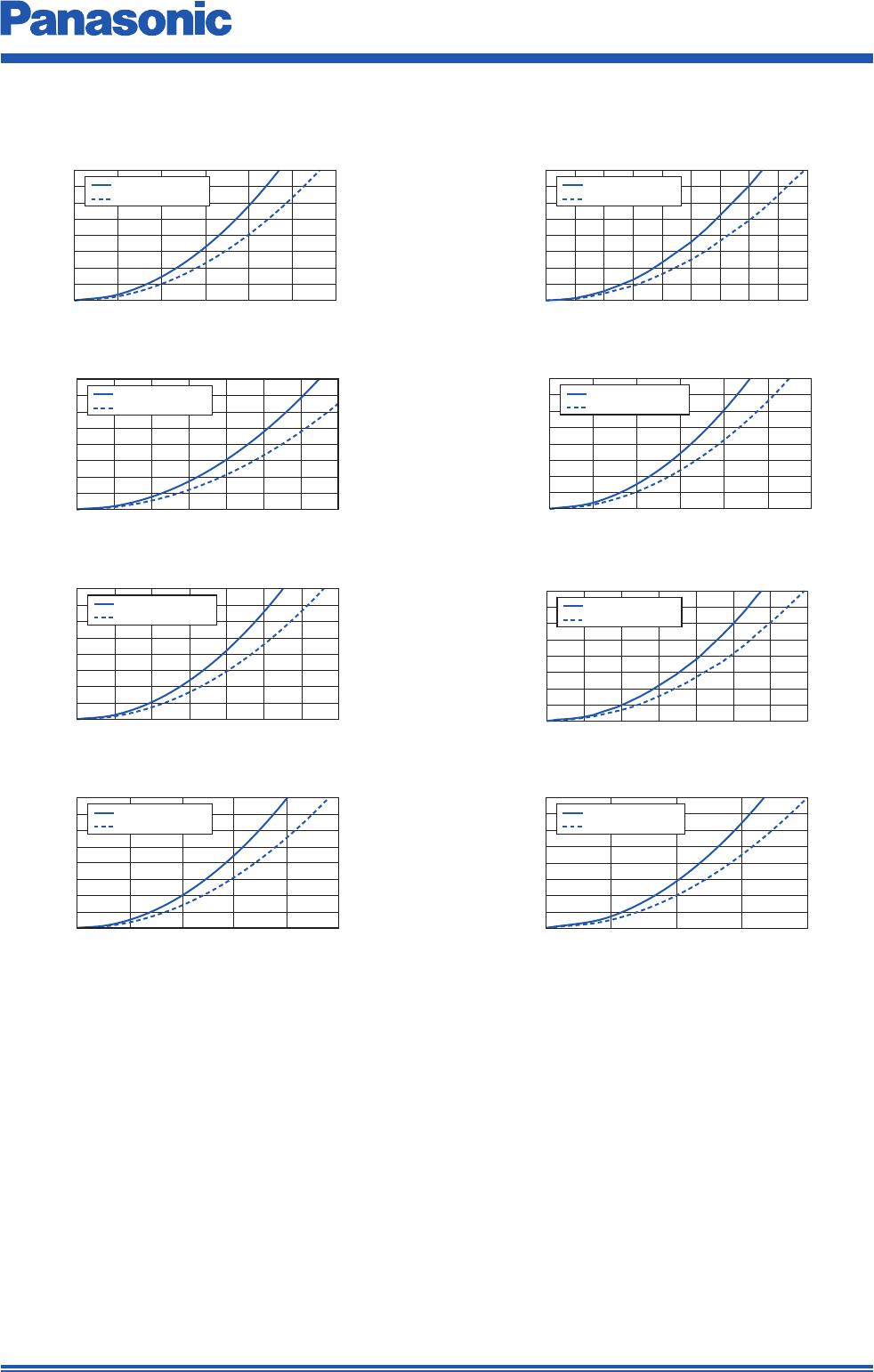
6. Series PCC-M1050ML/PCC-M1060ML (ETQP5M□□□YLC/ETQP6M□□□YLC)
(
1) Measured at 100 kHz.
(
2) DC current which causes temperature rise of 40 K. Parts are soldered by reflow on four-layer PWB (1.6 mm FR4)
and measured at room temperature. See also (
5)
(
3)
DC current which causes temperature rise of 40 K. Parts are soldered by reflow on multilayer PWB with high heat dissipation performance. Note: Heat radiation
constant are approx. 23 K/W measured on 10.9×10.0×5.0 mm case size and approx. 23 K/W measured on 10.9×10.0×6.0 mm case size. See also (
5)
(
4) Saturation rated current : Dc current which causes L(0) drop –30 %.
(
5) Within a suitable application, the part’s temperature depends on circuit design and certain heat dissipation
conditions. This should be double checked in a worst case operation mode.
In normal case, the max.standard operating temperature of +150 °C should not be exceeded.
For higher operating temperature conditions, please contact Panasonic representative in your area.
Series Part No.
Inductance
1
DCR (at 20 °C) (mΩ)
Rated Current (Typ. : A)
L0
(µH)
Tolerance
(%)
Typ.
(max.)
Tolerance
(%)
T=40K L=–30%
(
2) (
3) (
4)
PCC-M1050ML
[10.9×10.0×5.0(mm)]
ETQP5MR33YLC 0.33
±20
1.1(1.21)
±10
33.2 39.7 56.7
ETQP5MR68YLC 0.68 1.75(1.93) 26.3 31.5 40.0
ETQP5M1R0YLC 1.0 2.3(2.53) 23.0 27.5 37.8
ETQP5M2R0YLC 2.0 4.6(5.06) 16.2 19.4 31.3
PCC-M1060ML
[10.9×10.0×6.0(mm)]
ETQP6M1R5YLC 1.5 3.2(3.52) 19.5 23.3 32.0
ETQP6M2R5YLC 2.5 4.55(5.0) 16.3 19.6 25.8
ETQP6M3R3YLC 3.3 6.0(6.6) 14.2 17.0 26.3
ETQP6M4R7YLC 4.7 8.7(9.57) 11.8 14.1 22.5
ETQP5MR33YLC
ETQP6M1R5YLC
ETQP5MR68YLC
ETQP5M1R0YLC ETQP5M2R0YLC
ETQP6M2R5YLC
ETQP6M4R7YLCETQP6M3R3YLC
Inductance vs DC Current
Performance Characteristics (Ref er ence)
Dec. 201711
Design and specifications are each subject to change without notice. Ask factory for the current technical specifications before purchase and/or use.
Should a safety concern arise regarding this product, please be sure to contact us immediately.
Power Inductors
0
10
20
30
40
50
60
70
80
0 5 10 15 20 25 30 35
I
DC
(A)
ΔT(K)
PWB condition A
PWB condition B
I
DC
(A)
0
10
20
30
40
50
60
70
80
0 5 10 15 20
ΔT(K)
PWB condition A
PWB condition B
0
10
20
30
40
50
60
70
80
0 5 10 15 20 25 30
I
DC
(A)
ΔT(K)
PWB condition A
PWB condition B
0
10
20
30
40
50
60
70
80
010 20 30 5040 60
PWB condition A
PWB condition B
I
DC
(A)
ΔT(K)
I
DC
(A)
ΔT(K)
0
10
20
30
40
50
60
70
80
0 5 10 15 20 25 30 35 40 45
PWB condition A
PWB condition B
I
DC
(A)
ΔT(K)
0
10
20
30
40
50
60
70
80
04 81216202428
PWB condition A
PWB condition B
I
DC
(A)
0
10
20
30
40
50
60
70
80
0 5 10 15 20 25
ΔT(K)
PWB condition A
PWB condition B
I
DC
(A)
0
10
20
30
40
50
60
70
80
0 5 10 15 20 25 30 35
PWB condition A
PWB condition B
ΔT(K)
Case Temperature vs DC Current
PWB condition A : Four-layer PWB (1.6 mm FR4), See also (
2)
PWB condition B : Multilayer PWB with high heat dissipation performance. See also (
3)
ETQP5MR33YLC
ETQP6M1R5YLC
ETQP5MR68YLC
ETQP6M2R5YLC
ETQP5M1R0YLC ETQP5M2R0YLC
ETQP6M3R3YLC ETQP6M4R7YLC
Dec. 201711
Design and specifications are each subject to change without notice. Ask factory for the current technical specifications before purchase and/or use.
Should a safety concern arise regarding this product, please be sure to contact us immediately.
Power Inductors
Date Code Polarity
Inductance Suffix
7.5±0.4
7.0±0.4
3.0±0.3
2.0 2.0
H
0.1 min.
Date Code Polarity
Inductance Suffix
8.5±0.4
H
0.1 min.
2.02.0
3.0±0.3
8.0±0.4
Date Code Polarity
Inductance Suffix
10.7±0.5
10.0±0.4
4.2±0.3
2.0
2.0
H
0.1 min.
Date Code Polarity
Inductance Suffix
10.9±0.6
10.0±0.4
7.3±0.3
1.8
1.8
H
0.5 min.
Date Code Polarity
Inductance Suffix
5.5±0.4
5.0±0.4
3.0±0.3
1.21.2
H
0.1 min.
Date Code Polarity
Inductance Suffix
6.5±0.4
6.0±0.4
3.0±0.3
1.5 1.5
H
0.1 min.
Series PCC-M0754M
Series PCC-M0750M
(ETQP5M□□□YFM/YGM)
Series PCC-M0854M
Series PCC-M0850M
(ETQP5M□□□YFK/YGK)
Series PCC-M1054M
Series PCC-M1050M
(ETQP5M□□□YFC/YGC)
Series H
M1054M 5.4 max.
M1050M 5.0 max.
Series H
M0854M 5.4 max.
M0850M 5.0 max.
Series PCC-M1050ML
Series PCC-M1060ML
(ETQP5M□□□YLC/ETQP6M□□□YLC)
Series H
M1050ML 5.0 max.
M1060ML 6.0 max.
Series PCC-M0530M
Series PCC-M0540M
(ETQP3M□□□YFP/ETQP4M□□□YFP)
Series PCC-M0630M
Series PCC-M0645M
(ETQP3M□□□YFN/ETQP4M□□□YFN)
Series H
M0630M 3.0 max.
M0645M 4.5 max.
Series H
M0530M 3.0 max.
M0540M 4.0 max.
Dimensional tolerance unless noted : ±0.5
Dimensions in mm (not to scale)
Series H
M0754M 5.4 max.
M0750M 5.0 max.
Dec. 201711

ETQ-P5M470YFM

Mfr. #:
Manufacturer:
Panasonic
Description:
Fixed Inductors 49uH 20% 156mohm 1A CHOKE
Lifecycle:
New from this manufacturer.
Delivery:
DHL FedEx Ups TNT EMS
Payment:
T/T Paypal Visa MoneyGram Western Union