Design and specifications are each subject to change without notice. Ask factory for the current technical specifications before purchase and/or use.
Should a safety concern arise regarding this product, please be sure to contact us immediately.
Power Inductors
Inductance (µH)
I
DC
(A)
0
2
4
6
8
10
12
04268 1610 12 14
I
DC
(A)
0
10
20
30
40
50
60
70
80
04 8121620
ΔT(K)
PWB condition A
PWB condition B
PWB condition A
PWB condition B
Inductance (µH)
I
DC
(A)
0.0
0.5
1.0
1.5
2.0
2.5
3.0
05 1510 2520 30
I
DC
(A)
ΔT(K)
0
10
20
30
40
50
60
70
80
0246810
PWB condition A
PWB condition B
I
DC
(A)
ΔT(K)
0
10
20
30
40
50
60
70
80
0 0.5 1.0 1.5 2.0 2.5 3.0
PWB condition A
PWB condition B
I
DC
(A)
ΔT(K)
0
10
20
30
40
50
60
70
80
01 23 45
PWB condition A
PWB condition B
0
10
20
30
40
50
60
70
80
02 5713468
I
DC
(A)
ΔT(K)
PWB condition A
PWB condition B
I
DC
(A)
ΔT(K)
0
10
20
30
40
50
60
70
80
01234567
PWB condition A
PWB condition B
Inductance (µH)
I
DC
(A)
0
20
40
60
80
100
120
01 2 534
Inductance (µH)
I
DC
(A)
0
10
20
30
60
40
50
024 68
I
DC
(A)
0.0
5
10
15
20
02 6410812
Inductance (µH)
Inductance (μH)
I
DC
(A)
0
5
10
15
20
25
0246 108
4. Series PCC-M0854M/PCC-M0850M (ETQP5M□□□YFK/ETQP5M□□□YGK)
Standard Parts
ETQP5M2R5YFK ETQP5M100YFK
ETQP5M101YGK
ETQP5M470YFK
ETQP5M150YFK
ETQP5M220YFK
ETQP5M101YGK
ETQP5M470YFK
ETQP5M150YFK
ETQP5M220YFK
(
1) Measured at 100 kHz.
(
2) DC current which causes temperature rise of 40 K. Parts are soldered by reflow on four-layer PWB (1.6 mm FR4)
and measured at room temperature. See also (
5)
(
3)
DC current which causes temperature rise of 40 K. Parts are soldered by reflow on multilayer PWB with high heat dissipation performance. Note: Heat radiation
constant are approx. 27 K/W measured on 8.5×8.0×5.4 mm case size and approx. 29 K/W measured on 8.5×8.0×5.0 mm case size. See also (
5)
(
4) Saturation rated current : DC current which causes L(0) drop –30 %.
(
5) Within a suitable application, the part’s temperature depends on circuit design and certain heat dissipation
conditions. This should be double checked in a worst case operation mode.
In normal case, the max.standard operating temperature of + 150 °C should not be exceeded.
For higher operating temperature conditions, please contact Panasonic representative in your area.
Series Part No.
Inductance
1
DCR (at 20 °C) (mΩ)
Rated Current (Typ. : A)
L0
(µH)
Tolerance
(%)
Typ.
(max.)
Tolerance
(%)
T=40K L=–30%
(
2) (
3) (
4)
PCC-M0854M
[8.5×8.0×5.4(mm)]
ETQP5M2R5YFK 2.5
±20
7.6(8.4)
±10
11.9 14.0 20.1
ETQP5M100YFK 10 33(37) 5.7 6.7 13.0
ETQP5M150YFK 15 48.2(53.1) 4.7 5.5 7.2
ETQP5M220YFK 22 63(70) 4.1 4.8 6.9
ETQP5M470YFK 48 125(138) 2.9 3.4 5.4
PCC-M0850M
[8.5×8.0×5.0(mm)]
ETQP5M101YGK 100 302(333) 1.7 2.1 3.0
Performance Characteristics (Ref er ence)
Case Temperature vs DC Current
PWB condition A : Four-layer PWB (1.6 mm FR4), See also (
2)
PWB condition B : Multilayer PWB with high heat dissipation performance. See also (
3)
Inductance vs DC Current
Dec. 201711
Design and specifications are each subject to change without notice. Ask factory for the current technical specifications before purchase and/or use.
Should a safety concern arise regarding this product, please be sure to contact us immediately.
Power Inductors
I
DC
(A)
0
10
20
30
40
50
80
60
70
0245713 689
Inductance (µH)
I
DC
(A)
0
10
20
30
40
50
60
0246810
Inductance (µH)
Inductance (µH)
I
DC
(A)
0
1
2
3
4
0 5 10 15 20 3025
Inductance (µH)
I
DC
(A)
0.0
0.5
1.0
1.5
2.0
2.5
3.0
010203040
I
DC
(A)
0
0.4
0.8
1.2
1.6
010203040
Inductance (µH)
Inductance (µH)
I
DC
(A)
0
1
2
3
5
4
6
0 5 10 15 20
Inductance (µH)
I
DC
(A)
0
5
10
15
20
25
0246 108
Inductance (µH)
I
DC
(A)
0
2
4
6
8
10
12
02468 1610 12 14
I
DC
(A)
0
10
20
30
40
0246810
Inductance (µH)
Inductance (µH)
I
DC
(A)
0
20
40
60
80
100
120
01234 657
Standard Parts
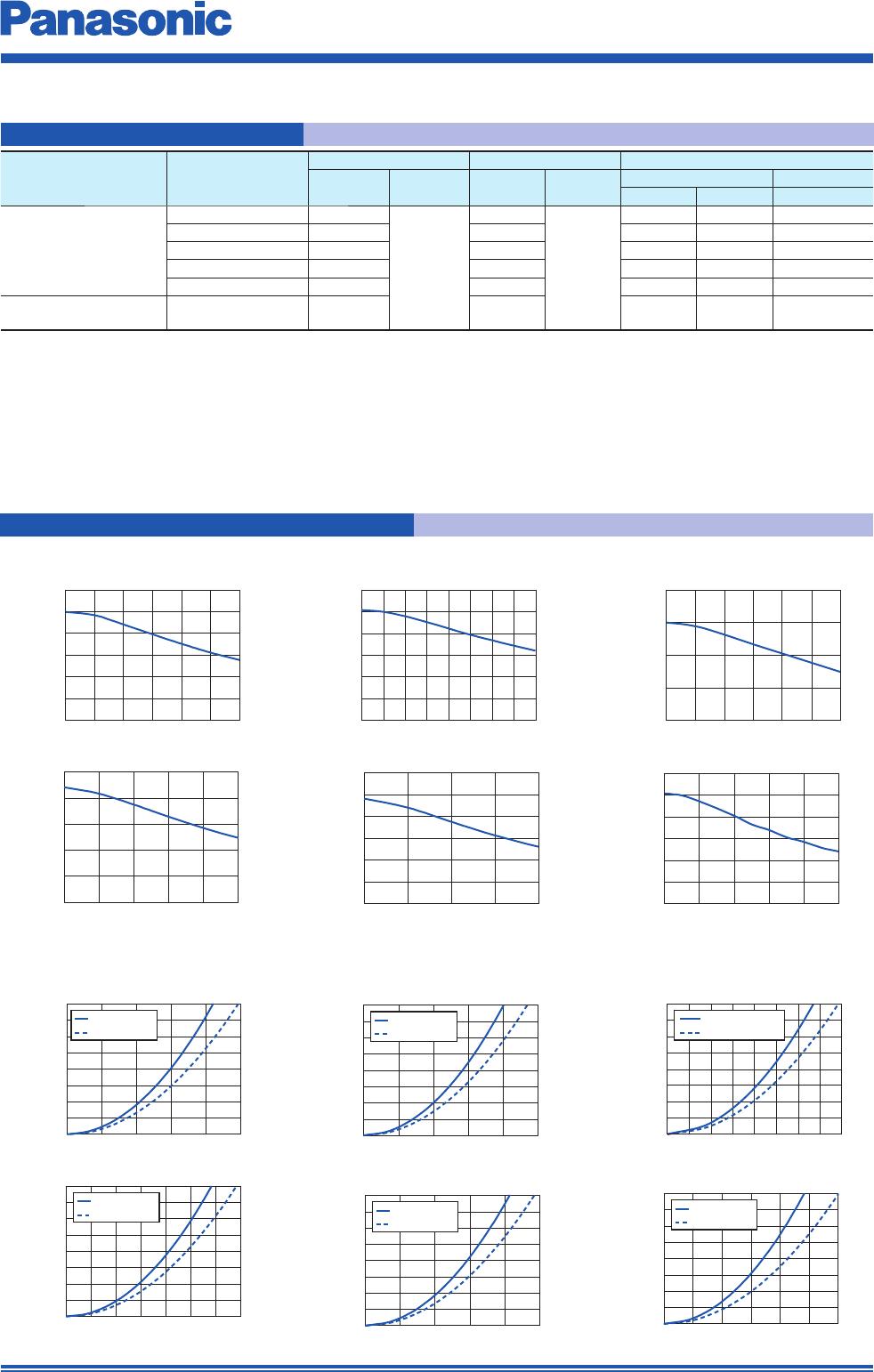
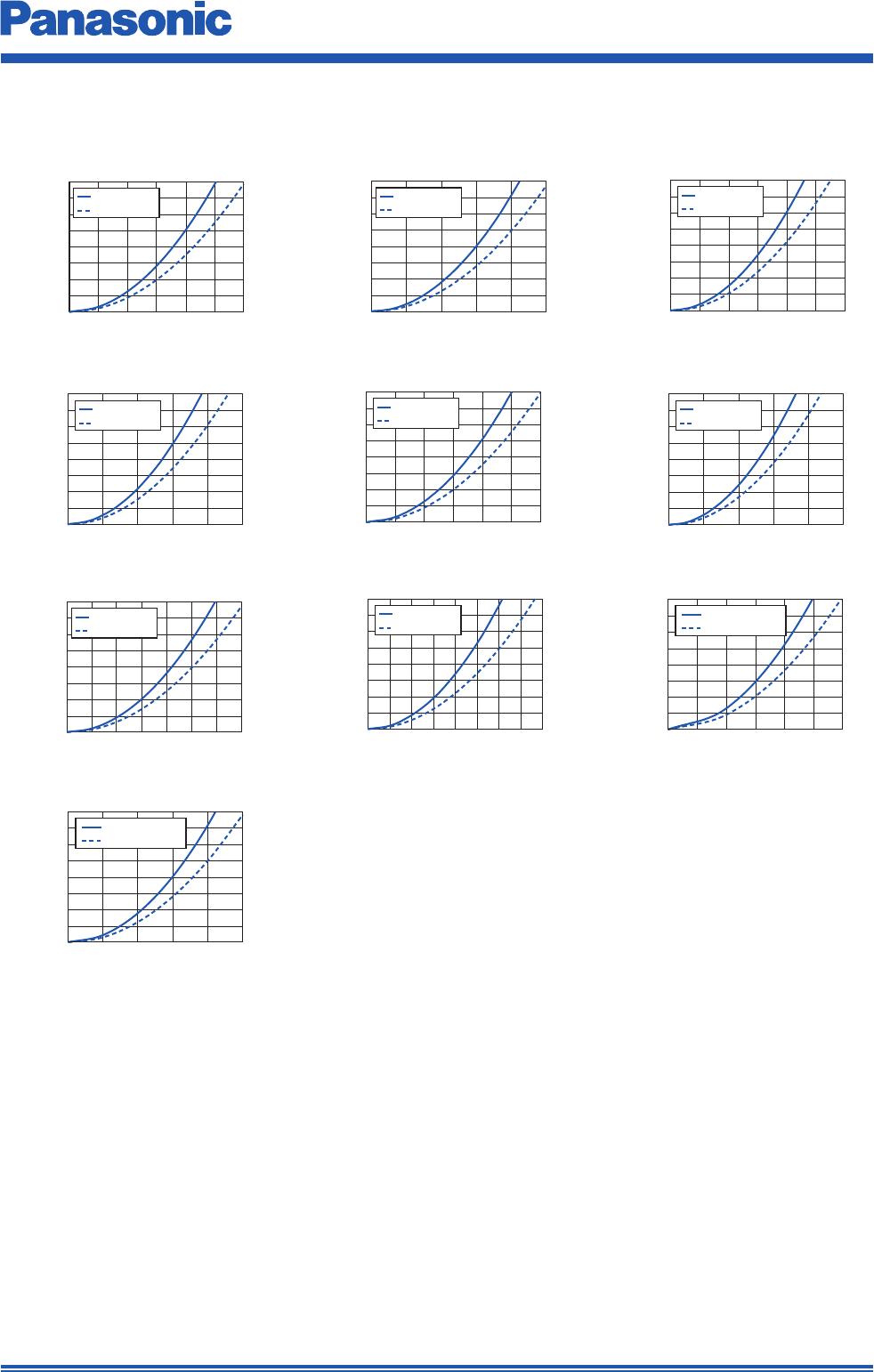
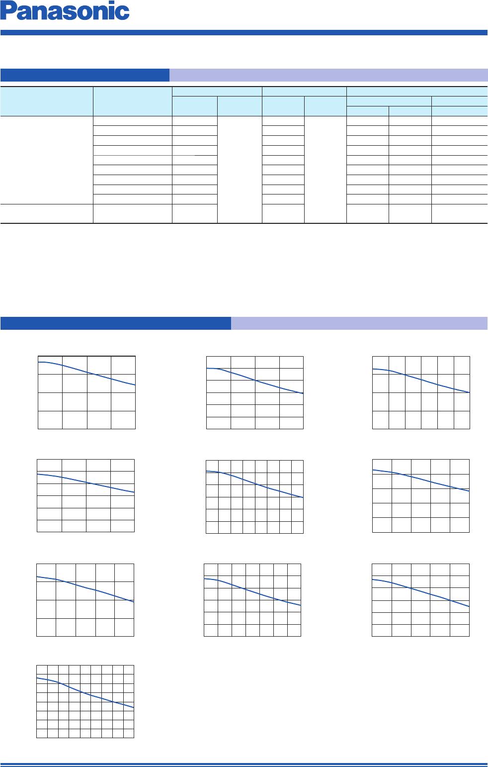
5. Series PCC-M1054M/PCC-M1050M (ETQP5M□□□YFC/ETQP5M□□□YGC)
Inductance vs DC Current
(
1) Measured at 100 kHz.
(
2) DC current which causes temperature rise of 40 K. Parts are soldered by reflow on four-layer PWB (1.6 mm FR4)
and measured at room temperature. See also (
5)
(
3)
DC current which causes temperature rise of 40 K. Parts are soldered by reflow on multilayer PWB with high heat dissipation performance. Note: Heat radiation
constant are approx. 23 K/W measured on 10.7×10.0×5.4 mm case size and approx. 26 K/W measured on 10.7×10.0×5.0 mm case size. See also (
5)
(
4) Saturation rated current : Dc current which causes L(0) drop –30 %.
(
5) Within a suitable application, the part’s temperature depends on circuit design and certain heat dissipation
conditions. This should be double checked in a worst case operation mode.
In normal case, the max.standard operating temperature of +150 °C should not be exceeded.
For higher operating temperature conditions, please contact Panasonic representative in your area.
Series Part No.
Inductance
1
DCR (at 20 °C) (mΩ)
Rated Current (Typ. : A)
L0
(µH)
Tolerance
(%)
Typ.
(max.)
Tolerance
(%)
T=40K L=–30%
(
2) (
3) (
4)
PCC-M1054M
[10.7×10.0×5.4(mm)]
ETQP5M1R5YFC 1.45
±20
3.8(4.2)
±10
17.9 21.4 35.1
ETQP5M2R5YFC 2.5 5.3(5.9) 15.1 18.1 27.2
ETQP5M3R3YFC 3.3 7.1(7.9) 13.1 15.7 22.7
ETQP5M4R7YFC 4.7 10.2(11.3) 10.9 13.1 20.0
ETQP5M100YFC 10 23.8(26.2) 7.1 8.5 10.7
ETQP5M220YFC 22 45(50) 5.2 6.2 8.8
ETQP5M330YFC 32.5 68.5(75.4) 4.2 5.0 7.6
ETQP5M470YFC 47 99(108.9) 3.5 4.2 6.8
ETQP5M680YFC 66
136(149.6)
3.0 3.6 4.9
PCC-M1050M
[10.7×10.0×5.0(mm)]
ETQP5M101YGC 97 208(229) 2.2 2.7 3.0
ETQP5M2R5YFC ETQP5M3R3YFC
ETQP5M4R7YFC ETQP5M100YFC ETQP5M220YFC
ETQP5M330YFC
ETQP5M680YFC
ETQP5M101YGC ETQP5M470YFC
ETQP5M1R5YFC
Performance Characteristics (Ref er ence)
Dec. 201711
Design and specifications are each subject to change without notice. Ask factory for the current technical specifications before purchase and/or use.
Should a safety concern arise regarding this product, please be sure to contact us immediately.
Power Inductors
0
10
20
30
40
50
60
70
80
01 2 3 45
I
DC
(A)
ΔT(K)
PWB condition A
PWB condition B
0
10
20
30
40
50
60
70
80
012 34 65
I
DC
(A)
ΔT(K)
PWB condition A
PWB condition B
I
DC
(A)
ΔT(K)
0
10
20
30
40
50
60
70
80
0 5 10 2015 25 30
PWB condition A
PWB condition B
I
DC
(A)
0
10
20
30
40
50
60
70
80
0 5 10 15 20 25
ΔT(K)
PWB condition A
PWB condition B
I
DC
(A)
ΔT(K)
0
10
20
30
40
50
60
70
80
04 81216 2420
PWB condition A
PWB condition B
I
DC
(A)
ΔT(K)
0
10
20
30
40
50
60
70
80
04812 2016
PWB condition A
PWB condition B
I
DC
(A)
ΔT(K)
0
10
20
30
40
50
60
70
80
02 46 8 1210
PWB condition A
PWB condition B
I
DC
(A)
ΔT(K)
0
10
20
30
40
50
60
70
80
0246810
PWB condition A
PWB condition B
I
DC
(A)
0
10
20
30
40
50
60
70
80
012 43657
ΔT(K)
PWB condition A
PWB condition B
I
DC
(A)
ΔT(K)
0
10
20
30
40
50
60
70
80
0 0.5 1.0 1.5 2.0 2.5 4.03.0 3.5
PWB condition A
PWB condition B
Case Temperature vs DC Current
PWB condition A : Four-layer PWB (1.6 mm FR4), See also (
2)
PWB condition B : Multilayer PWB with high heat dissipation performance. See also (
3)
ETQP5M2R5YFC ETQP5M3R3YFC
ETQP5M4R7YFC ETQP5M100YFC ETQP5M220YFC
ETQP5M101YGC ETQP5M470YFCETQP5M330YFC
ETQP5M680YFC
ETQP5M1R5YFC
Dec. 201711

ETQ-P5M470YFM

Mfr. #:
Manufacturer:
Panasonic
Description:
Fixed Inductors 49uH 20% 156mohm 1A CHOKE
Lifecycle:
New from this manufacturer.
Delivery:
DHL FedEx Ups TNT EMS
Payment:
T/T Paypal Visa MoneyGram Western Union