Design and specifications are each subject to change without notice. Ask factory for the current technical specifications before purchase and/or use.
Should a safety concern arise regarding this product, please be sure to contact us immediately.
Power Inductors
I
DC
(A)
0
2
4
6
8
10
12
04812142 6 10 16
Inductance (µH)
I
DC
(A)
0
20
40
60
100
80
045123
Inductance (µH)
I
DC
(A)
0.0
1.0
2.0
3.0
4.0
5.0
8.0
7.0
6.0
04812162 6 10 14
Inductance (µH)
Inductance (µH)
I
DC
(A)
0.0
1.0
2.0
3.0
4.0
5.0
6.0
0 5 10 15 20
Inductance (µH)
I
DC
(A)
0
5
10
15
20
25
0246 108
Inductance (µH)
I
DC
(A)
0
10
20
30
40
024 68
Inductance (µH)
I
DC
(A)
0
10
20
30
40
50
60
0123 645
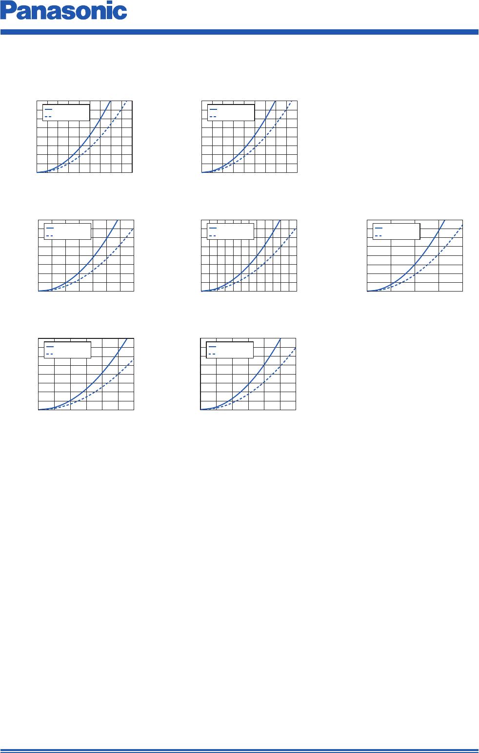
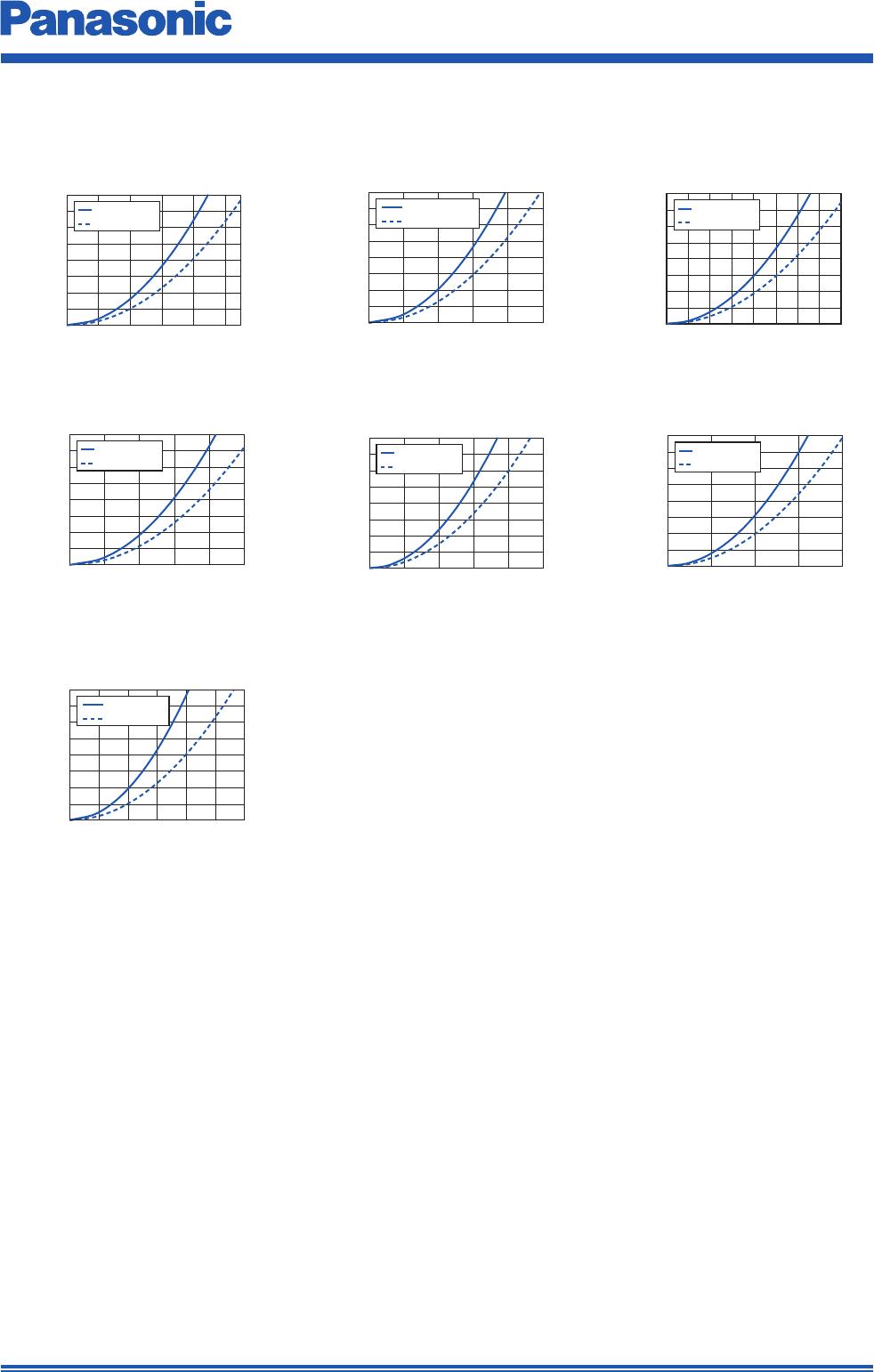
● Inductance vs DC Current
3. Series PCC-M0754M/PCC-M0750M (ETQP5M□□□YFM/ETQP5M□□□YGM)
Series Part No.
Inductance
✽
1
DCR (at 20 °C) (mΩ)
Rated Current (Typ. : A)
L0
(µH)
Tolerance
(%)
Typ.
(max.)
Tolerance
(%)
△T=40K △L=–30%
(
✽
2) (
✽
3) (
✽
4)
PCC-M0754M
[7.5×7.0×5.4(mm)]
ETQP5M4R7YFM 4.7
±20
20(23)
±10
6.3 8.0 13.1
ETQP5M6R8YFM 6.8 26.7(29.4) 5.5 6.9 12.1
ETQP5M100YFM 10 37.6(41.3) 4.7 5.7 10.6
ETQP5M220YFM 22 92(102) 3.0 3.7 5.8
ETQP5M330YFM 33 120(132) 2.6 3.3 4.8
ETQP5M470YFM 48 156(172) 2.3 2.9 4.1
PCC-M0750M
[7.5×7.0×5.0(mm)]
ETQP5M101YGM 95
348(382.8)
1.4 1.9 3.1
(
✽
1) Measured at 100 kHz.
(
✽
2) DC current which causes temperature rise of 40 K. Parts are soldered by reflow on four-layer PWB (1.6 mm
FR4) and measured at room temperature. See also (
✽
5)
(
✽
3) DC current which causes temperature rise of 40 K. Parts are soldered by reflow on multilayer PWB with high
heat dissipation performance. Note: Heat radiation constant is approx. 31 K/W measured on 7.5×7.0×5.4 mm
case size and approx. 29 K/W measured on 7.5×7.0×5.0 mm case size. See also (
✽
5)
(
✽
4) Saturation rated current : DC current which causes L(0) drop –30 %.
(
✽
5) Within a suitable application, the part’s temperature depends on circuit design and certain heat dissipation
conditions. This should be double checked in a worst case operation mode.
In normal case, the max.standard operating temperature of +150 °C should not be exceeded.
For higher operating temperature conditions, please contact Panasonic representative in your area.
ETQP5M4R7YFM ETQP5M100YFM
ETQP5M470YFMETQP5M220YFM
ETQP5M101YGM
ETQP5M330YFM
ETQP5M6R8YFM
Performance Characteristics (Ref er ence)
Standard Parts
Dec. 201711